Button management by multiplexing, first part
published: 22 July 2021 / updated 27 July 2021

Preamble
On facebook, a member asked a question about the possibility of managing 8 buttons push buttons, this to control a model railway switch. He chose the soution of an assembly with voltage divider and connected to an input analog:
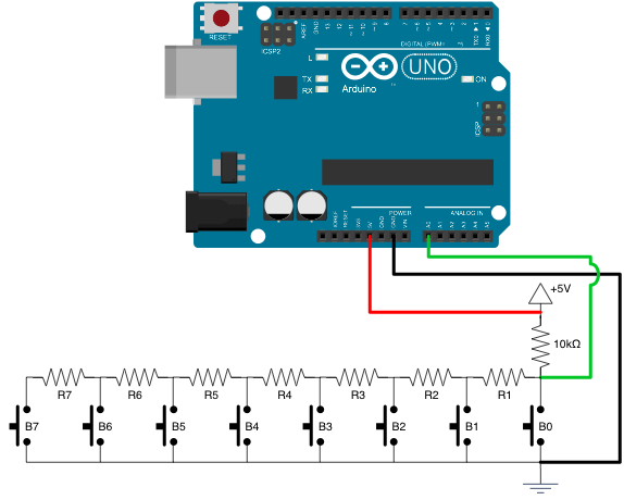
This solution may work. But it requires a fine control of the tensions to be analyzed so as not to assign a signal to the wrong button. In addition, we cannot activate several buttons simultaneously.
My solution uses a serial-parallel converter 74HC595. It is a simple component and at a very low price. We will see how to manage not a single converter, but two converters 4HC595:
- the first to analyze the position of 8 pushbuttons;
- the second to act on the environment according to the position of our push buttons.
The 74HC595 converter
Technical information on the 74HC595 converter:
Serial to parallel converter 74HC595
A 74HC595 circuit only needs three pins to function:
- DS: it is through this port that the data is injected bit by bit
- SH_CP: This is the port through which the clock signal is transmitted. This component needs a reference clock to understand and interpret the data;
- ST_CP: trigger. This is the port that we use to switch the data waiting to be updated. To use it, we just switch it to LOW before sending data, and we set it to HIGH to activate the transition of the register at the end of transmission.
In video the way in which a 74HC595 circuit is used:
Here is the connection diagram with an ARDUINO Nano card:
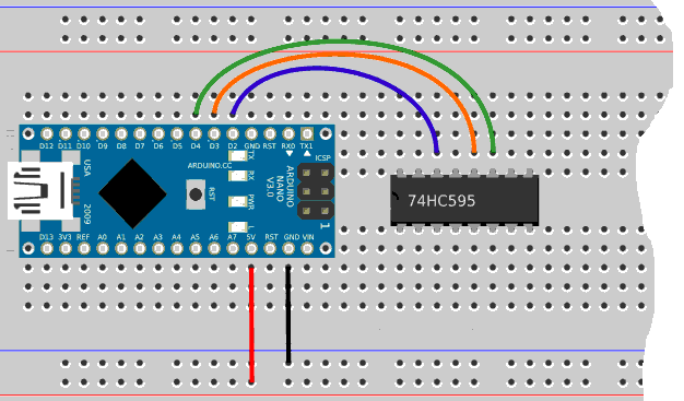
On this diagram, we have not put, for the moment, the supply lines from circuit 74HC595.
Here is the program, in FORTH language, allowing to initialize the PORT D of our card ARDUINO to communicate with the converter 74HC595:
\ include pinsDefinitions.txt

\ for Arduino NANO - port comm. with 74HC595
$2b constant PORTD

flash
\ SERial data
PORTD %00000100 defPIN: SER     \ PD2 -> pin 14 on the 74HC595

\ storage-Register CLocK 1
PORTD %00001000 defPIN: RCLK1   \ PD3 -> pin 12 on the  fist 74HC595

\ Shift-Register CLocK
PORTD %00010000 defPIN: SRCLK   \ PD4 -> pin 11 on the 74HC595
ram

\ init ports affected to 74HC595
: init.74HC595 ( ---)
    SER     output
    RCLK1   output
    SRCLK   output
    SER     low
    RCLK1   high
    SRCLK   low
  ;
Before compiling this code, compile the contents of this file:
ARDUINO pins definitions
The word init.74HC595 is used to initialize the PORT D to communicate
with the 74HC595 converter.
Installation of a second 74HC595 converter
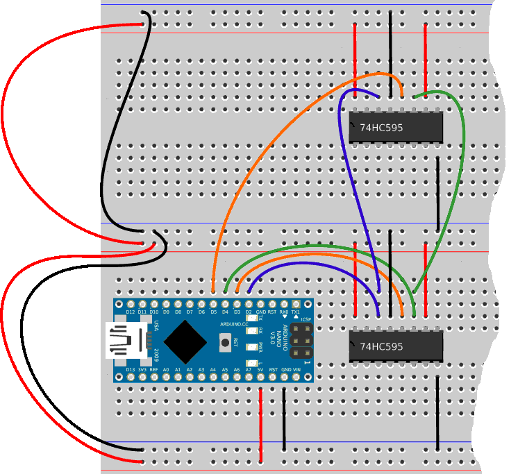
For the rest of our assembly, we need a second 74HC595 converter. We connect the supply lines of these two converters:

On each 74HC595 converter, you must then:
- force pin OE (pin 13) to zero
- force pin MR (pin 10) to one
- connect the ST_CP pin (pin 12) to another output of PORT D on the ARDUINO card
Here is the diagram of these new connections:
Pour prendre en compte ce second convertisseur 74HC595, on définit une nouvelle constante:
\ storage-Register CLocK 2
PORTD %00100000 defPIN: RCLK2   \ PD5 -> pin 12 on the second 74HC595
Et in modifie init.74HC595:
\ init ports affected to 74HC595
: init.74HC595 ( ---)
    SER     output
    RCLK1   output
    RCLK2   output
    SRCLK   output
    SER     low
    RCLK1   high
    RCLK2   high
    SRCLK   low
  ;
It's OK? Are you following that far?
So, now we're going to mount the LEDs and buttons like this:
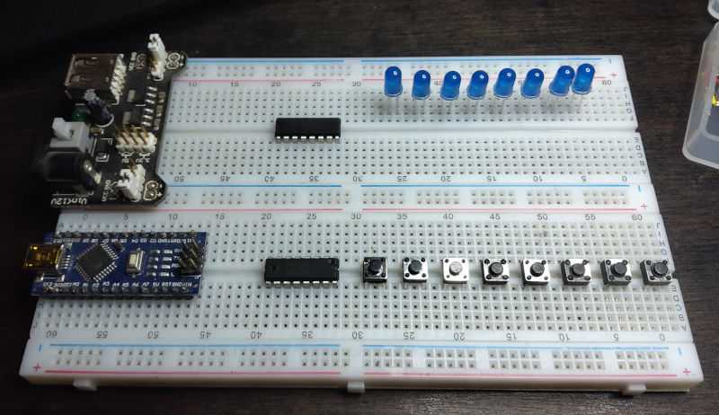
In this photo, there is no wiring. LEDs are installed here because that I have no relays or railway switches. These LEDs will allow you to control the correct operation of the 74HC595 converters.
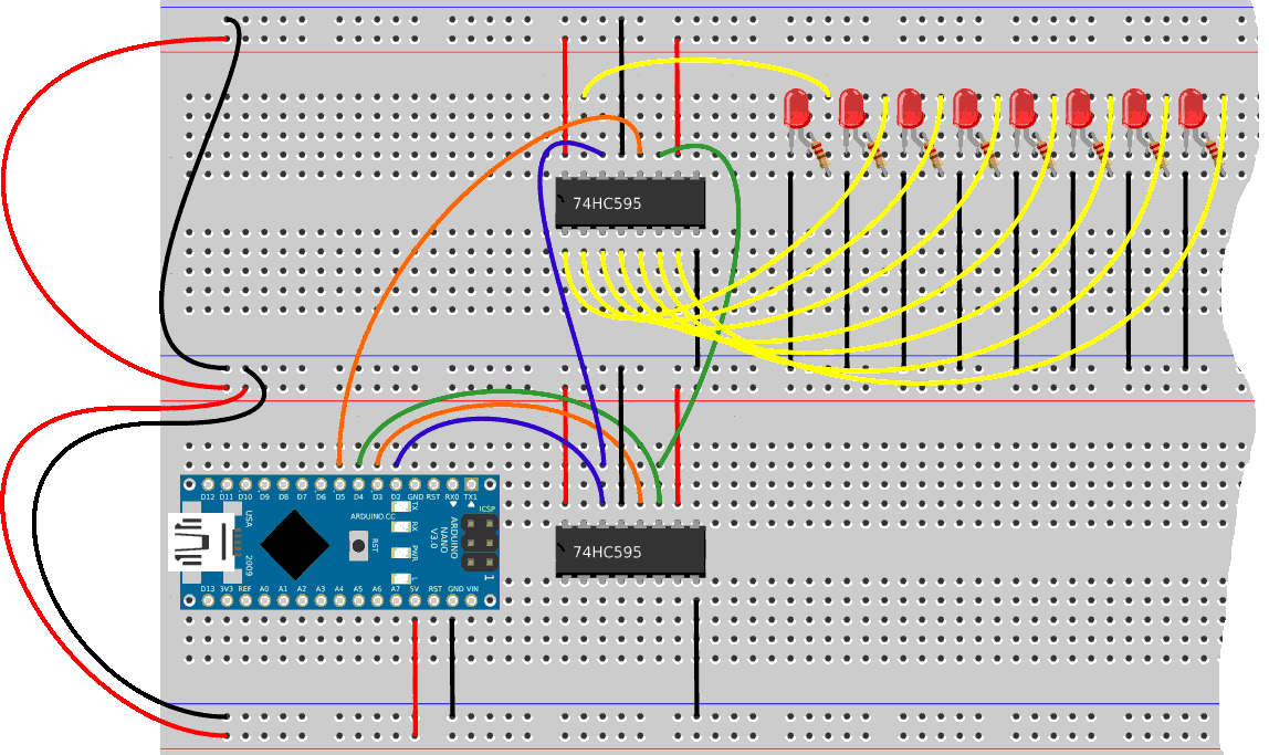
Mounting the LEDs
Each converter has outputs, denoted Q0 to Q7. Each LED must be wired to each of these outputs:
Let's build the words that will selectively activate these LEDs.
We start with the word csend which will transform a byte
in pulses:
: csend ( c ---)
    8 for
        1 r@ lshift             \ calculate binary mask
        over and                \ bit 0 or not 0
        if      SER high        \ datapin HIGH
        else    SER low         \ datapin LOW
        then
    next
    drop
  ;
The byte passed to csend is analyzed bit by bit. If a bit is at
1, the SER pin is switched to the high state. If this bit is at 0, this SER pin is toggled
low.
Once the bit is set to 1 or 0 on SER, the clock signal must be transmitted:
: csend ( c ---)
    8 for
        1 r@ lshift             \ calculate binary mask
        over and                \ bit 0 or not 0
        if      SER high        \ datapin HIGH
        else    SER low         \ datapin LOW
        then
        SRCLK high              \ clockPin HIGH
        SRCLK low               \ clockPin LOW
    next
    drop
  ;
The SRCLK output is set high then low.
We still have to deal with the selection of the 74HC595 converter. We go
embed our word csend in a higher level word:
: toLeds ( c -- )
    RCLK2 low                   \ latchPin LOW
    csend
    RCLK2 high                  \ latchPin HIGH
  ;
We select the 74HC595 converter which manages the LEDs by setting the low state output RCLK2.
It is possible to serialize the 74HC595 converters. But button management and LEDs (or relays) would have been more difficult to manage. By simply adding a thread RCLK on the ARDUINO card, select the converter to manage.
To test the LEDs, we will execute:
init.74HC595
1 128 + toLeds
will light up the LEDs connected to Q0 and Q7:
Our project is to manage these LEDs (and later relays) from push buttons. We will now take care of these buttons.
Push buttons mounting
The connection of the buttons follows the same logic as the assembly of the LEDs. These buttons let the high signal pass if they are active. Their release interrupts the signal. The idea is to connect them like this:
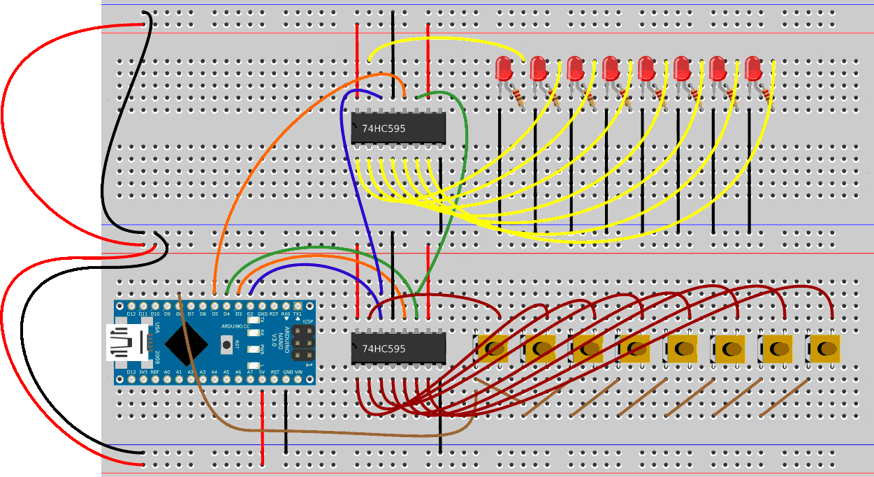
The button inputs are connected to outputs Q0 to Q7 of the converter 74HC595. The outputs of the buttons are pooled. This pooling is connected at port PB0 (D8).
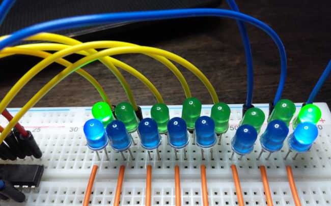
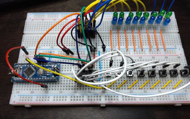
Here is the aspect of the finished assembly. In this photo, the LED resistors have been replaced by LEDs mounted in series in groups of two:
We will see in the second part of our article how to manage these buttons and LEDs:
Button management by multiplexing, second part.
Complete code is available here: