Button management by multiplexing, second part
published: 27 July 2021 / updated 27 July 2021

Multiplexing management
Summary. We have eight buttons, each button being connected to an output of a serial / parallel converter 74HC595. These eight buttons have an output set common and connected to a digital input on the ARDUINO card. We will start by testing this digital input. To do this, we will define:
\ input pin - buttons output
$25 constant PORTB
flash
PORTB %00000001 defPIN: BUTTONS \ PB0 (8)
ram

\ init. PORT B PB0
: init.buttons ( ---)
    BUTTONS input
  ;
To eliminate unwanted signals, we add a 10K resistor and a LED between pin PB0 and GND:
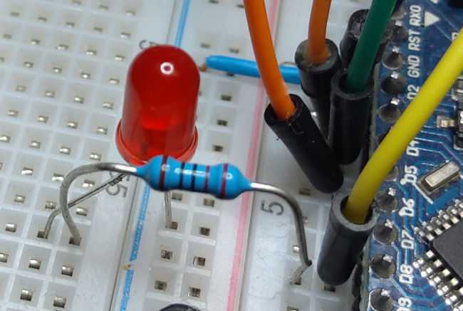
This resistor and this LED are connected in series. Their goal is to force entry PB0 at low level if no signal arrives from the buttons. The LED has a role of indicator signal. If you press a button, it should light up. To test the good connection of the buttons, we define:
\ set all bits to high level on buttons input
: FFtoButtons ( -- )
    255 toButtons
  ;
Executing FFtoButtons sends a high level signal on
inputs for all buttons. We can therefore test the buttons if
these are correctly supplied. You have to press button by button:
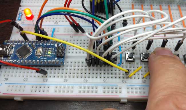
By successively pressing each button, the LED connected to PB0 must light up. To selectively check a single button, we will inject a value corresponding to an exponent of 2:
  1 toButtons  \ LED on PB0 ON only if button 0 pressed
  2 toButtons  \ LED on PB0 ON only if button 1 pressed
  4 toButtons  \ LED on PB0 ON only if button 2 pressed
  8 toButtons  \ LED on PB0 ON only if button 3 pressed
\ ....
128 toButtons  \ LED on PB0 ON only if button 7 pressed
If the buttons are correctly supplied, it is not possible to light the LED in PB0
only by pressing the powered button. For example, the sequence 4 toButtons
will only power the 3rd button (button 2). Only pressing this button will turn on the LED. The
other buttons must leave the LED in PB0 off.
The buttons are numbered from 0 to 7.
We understand, by the course of the explanations, how much the programming language FORTH provides ease of debugging, both hardware and software.
With FORTH. No compilation apart from the ARDUINO map. No upload. The code is injected through the terminal. We can run any word to test the proper functioning of our assembly.
Button scan
To know if a button is activated, a button by button signal must be injected.
This injection value is always an exponent of 2, included in the interval
1..128. Here is a loop that will generate these exponents from the word lshift:
: buttonsScan ( -- )
    8 for
        r@ .
    next
  ;
As is, the word buttonsScan will simply display the index values
of the for next loop: 7 6 5 4 3 2 1 0.
It is this index which will allow us to shift to the left a bit in a byte.
For example: 1 3 lshift shifts three positions, leaving the value
8 on the stack. Let's modify buttonsScan:
: buttonsScan ( -- )
    8 for
        1 r@ lshift .
    next
  ;
Running buttonsScan displays: 128 64 32 16 8 4 2 1.
Now, we will inject these values into our converter instead of displaying them the value. For our test, we will inject these values into our ramp of LEDs and set a time delay:
: buttonsScan ( -- )
    8 for
        1 r@ lshift   toLeds
        300 ms
    next
  ;
The powers of two in binary
The values 1 2 4 8 16 ... 128 are not chosen at random. The smallest storage unit memory is byte. It is an area which is 8 bits:
x x x x x x x x
Here, each "x" is a bit. From left to right, each bit has this position:
  x x x x x x x x
  7 6 5 4 3 2 1 0
We call it the weight of a bit. We modify the bit of weight 3 by setting it to 1:
  x x x x 1 x x x
  7 6 5 4 3 2 1 0
In decimal, our byte will therefore have the value 2 EXP n where n is the weight of our bit.
The result of 2 EXP 3 is 8.
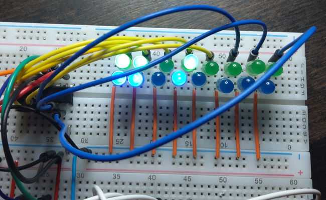
Executing buttonsScan successively lights our LEDs, starting
from the left. We now modify our code to inject the values into the buttons
instead of LEDs. In passing, we will test the state of PB0:
: buttonsScan ( -- )
    8 for
        1 r@ lshift   toButtons
        BUTTONS pin@
        if
            r@ .
        then
    next
  ;
Running buttonsScan displays a value between 0 and 7
if a button is activated. It does not display anything if no button is activated.
Arrived here, we will start to take care of our LEDs.
LED management
On our assembly, we have LEDs. But keep in mind that the initial problem consists of managing railway switches. These turnouts are activated by electromagnets. If the electromagnet is active, the train changes direction. Yes the electromagnet is deactivated, the train does not change direction.
The idea is therefore to make the position of a turnout stable each time you press the corresponding button:
| button bouton | rel./LED |
|---|---|
| 0 | 0 |
| 1 | 1 |
| 0 | 1 |
| 1 | 0 |
We are typically in a sequential logic. The push of a button changes the state of the corresponding relay/LED. This state remains stable until the next press of this button.
We are going to manage a variable corresponding to the state of these relays/LEDs:
variable LEDs    \ store result of active buttons

\ toggle LED state, c value 1 or 2 or 4.. 128
: toggleLED ( c --- )
    dup LEDs mtst       \ test if bit = 1
    if      LEDs mclr   \ clear bit
    else    LEDs mset   \ set bit
    then
  ;
The LEDs variable is managed bit by bit using the word toggleLED.
The value of c is a power of 2 between 1 and 128.
We position an LED of row n like this:
\ set LED state. n between 0..7
: setLED ( n -- )
    1 swap lshift   \ convert n to 2 EXP n
    toggleLED       \ toggle LED/relay state
    LEDs @ toLeds   \ change LEDs/relay state
  ;
This word setLED accepts as parameter a value within the range
0..7. This parameter corresponds to the position of the scanned button. Word test
setLED:
0 toLeds        \ set all LEDs OFF
1 setLED
0 setLED
3 setLED
Result:
We just have to modify buttonsScan like this:
: buttonsScan ( -- )
    8 for
        1 r@ lshift   toButtons
        BUTTONS pin@    \ button activated?
        if
            r@ setLED
        then
    next
  ;
Complete code is available here: