Interrupted LED flashing
published: 14 June 2019 / updated 22 June 2019

Blinking of an LED
This topic has already been discussed here: ARDUINO ports: turning on an LED.
Here the word that manages this blink:
: clignote ( ---)       \ boucle de clignotement
    init-ddrb
    begin
        led13-on   500 ms
        led13-off  500 ms
    key? until ;
The disadvantage of this program, purely didactic, is that it can not do
only that. And immobilize an ARDUINO card just to flash an LED, that's
a real mess! Because in the loop begin .. until we manage a delay
500 milliseconds, a delay that prevents any other action.
By properly handling interrupts, we will be able to release this machine time fruitfully.
Turn LED on and off
Here is the minimum code for managing the LED connected to connector 13:
\ Port Register Definitions
$24 constant DDRB       \ Direction Data Register PORT B
$25 constant PORTB      \ data in PORT B

%10000000 constant pLED \ mask for LED connector 13 (onboard LED)

: toggleLed   ( --- )   \ toggle LED off if LED is on, and inverse...
  PORTB c@              \ get LED status
  pLED xor              \ invert bit x0000000
  PORTB c!              \ turn ON or OFF led
;
You can test this code immediately after compiling it:
pLED DDRB c!            \ positionne DDRB en sortie pour led 13
toggleLed               \ si LED éteinte, elle s'allume
toggleLed               \ si LED allumée, elle s'éteint
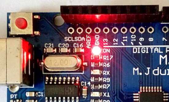
No electrical diagram. We will only manage this LED already mounted on the ARDUINO board.
The TIMER interrupt
A timer is a TCNTx register in the microcontroller. It is incremented each time an impulse is received clock. This clock signal may be specific to the microcontroller or external. A timer is a counter capable of counting the time that elapses.
The timer register we are interested in, TCNT3 has 8 bits. He is able to count from 0 to 255 (from 00 to FF in hexadecimal). When it reaches 255, an additional clock tick makes it pass to 256, but since it is impossible, this register having only 8 bits, it returns to zero. The TIFRx register experiences an overflow, which causes a special bit to be set in 1 the control register associated with the timer.
We define:
$91 constant TCCR3B     \ Timer/Counter3 Control Register B
$71 constant TIMSK3     \ Timer/Counter3 Interrupt Mask Register
36 constant ovf3Ivec    \ interrupt vector
Then we define a variable counter:
\ Counter for timer overflows
variable counter
With each overflow of the TIMER interrupt, this variable will be incremented:
\ The interrupt routine
: t3OverflowIsr ( ---)
    1 counter +!                    \ increment counter
;i
WARNING : the word t3OverflowIsr should not be
performed in interpretation. You will notice that it ends with ; i
while "colon" definitions always end with ;
We prepare the initialization of the TIMER interrupt:
: irqOvf3Init ( ---)
    ['] t3OverflowIsr ovf3Ivec int! \ Store the interrupt vector
    1 TCCR3B mset                   \ Activate counter 3
    1 TIMSK3 mset                   \ Activate timer3 overflow interrupt
;
Et voilà! On peut tester notre interruption:
$80 DDRB c!             \ init DDRB in OUTPUT mode
irqOvf3Init             \ init TIMER interrupt
counter @ .             \ fetch counter value and display it
#1000 ms                \ wait 1 sec.
counter @ .             \ fetch counter value
If the value of counter has evolved, we have confirmation
that the TIMER interrupt is operational.
Manage LED blinking with our interruption
We repeat our definition:
: t3OverflowIsr ( ---)
    1 counter +!                    \ increment counter
;i
We will add the blinking management of our LED:
: t3OverflowIsr ( ---)
    1 counter +!                    \ increment counter
    counter @ 500 >                 \ test if counter up to 500
    if
        0 counter !                 \ reset counter
        toggleLed                   \ toggle LED on or off
    then
;i
Recompile the entire program. Then execute this:
$80 DDRB c!             \ init DDRB in OUTPUT mode
irqOvf3Init             \ init TIMER interrupt
Look at the LED on the ARDUINO board. She's blinking! There is nothing else to do...
Oh yes!
If you recompile the program, you must first execute this new word:
irqOvf3Dis:
: irqOvf3Dis ( ---)                 \ Disable interrupt
    1 TIMSK3 mclr
;
The complete listing is available here: Clignotement LED par interruption timer 03