Manage a gate alarm by interrupt
published: 15 November 2020 / updated 16 November 2020

Preamble
It all started with a request from an ARDUINO programmer who wrote his code by a friend:
#include <Arduino.h>
#include <Wire.h>
#include <SoftwareSerial.h>
#include <LiquidCrystal_I2C.h>
/*  Déclaration de l'écran LCD  */
LiquidCrystal_I2C lcd(0x27,16,2);
/*  Déclaration des variables  */
bool portail_ferme = false;
bool portail_ouvert = false;
/*  Paramétrage des différentes broche  */
void setup(){
    lcd.init();
    lcd.home();
    lcd.clear();
    lcd.backlight();
    pinMode(9,INPUT);
    pinMode(10,OUTPUT);
    pinMode(13,OUTPUT);
}
/*  Traitement  */
void loop(){
    if(((digitalRead(9))==(1))){
        digitalWrite(10,1);
        tone(13,440,2000); // write to buzzer
        if (portail_ouvert == false){
          portail_ouvert = true;
          portail_ferme = false;
          lcd.clear();
          lcd.print( " portail  ouvert " );
        }
        delay(2000);
        _delay(1);
    }else{
        digitalWrite(10,0);
        if (portail_ferme == false){
          portail_ouvert = false;
          portail_ferme = true;
          lcd.clear();
          lcd.print( " portail  ferme" );
        }
    }
}
void _delay(float seconds){
  long endTime = millis() + seconds * 1000;
  while(millis() < endTime)_loop();
}
void _loop(){}
Functionally, this program simply does this:
- if the gate contactor is at 1, the gate is considered as "open":
- we send the message "portal open"
- the buzzer sounds
- if the gate contactor is at 0, the gate is considered "closed":
- we send the message "gate closed"
- the buzzer no longer rings
The problem with the C language program is that it does just that, in a endless loop. Unfortunately, this is a classic mistake for the novice programmer.
The FORTH solution with interruption
With FlashForth on ARDUINO NANO, we will use a hardware interrupt.
On the gate side, we mount a contactor of this type:

This contactor has two outputs:
- output ON low state
- output ON high state
Each output changes state depending on whether or not this switch is pressed.
For the gate, we have chosen the output which is OFF when the contactor is pressed. Opening the gate switches the selected output to the ON state when the contactor is released. We therefore have the following truth table:
- Contact == 0: gate closed
- Contact & lt;> 0: portal open
This is how this contactor is connected to our ARDUINO NANO card:
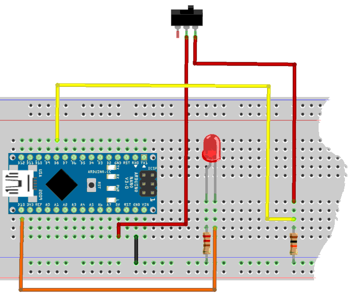
The contactor is supplied with 5V. Contactor output is returned to PBO (8) which is an input controlling PCINT0.
Here, on the assembly, the LED indicates the state of the alarm when the gate is open. On the actual assembly, we leave it to you to connect buzzer, flashing light and display.
Before handling the interruption, here is how to handle our portal contact.
Portal contact management
In this program, we do not take care of the display or the buzzer. We leave you the pleasure of adding these features.
-defPin
marker -defPin
\ require pinsDefinitions.txt - source:
\ https://github.com/MPETREMANN11/ARDUINO-FORTH/blob/master/pinsDefinitions.txt

-alarm
marker -alarm

\ Registers for ALARM
$25 constant PORTB
flash
PORTB %00100000 defPIN: ALARM  ( portB PB5)
PORTB %00000001 defPIN: BUTTON ( portB PB0)
ram

: tempo ( ---)
   3000 for next ; \ adjust the value 3000 if necessary

: alarm-test ( ---)
    BUTTON pin@
    tempo
    if      ALARM high
    else    ALARM low
    then
  ;
We can test the proper functioning of alarm-test. If the button
is active, the alarm is high. It is after ALARM high
that you can add the words that display the state of the portal, as well as the
triggering of the buzzer.
We encapsulate our word alarm-test in the definition of alarm-action:
: alarm-action ( ---)
    di  \ disable interrupt
    alarm-test
    ei  \ ei = Enable Interrupt
  ;i
The word alarm-action must not be executed from the terminal. It is this word which
will be executed by the hardware interrupt.
Interrupt setting
The interrupt setting applies to the button connected to the bit B0 from PORTB. This bit triggers the PCINT0 interrupt.
-interr
marker -interr

\ EXTERNAL_INTERRUPT
$0004 constant PCINT0addr   \ Pin Change Interrupt Request 0
$6b constant PCMSK0         \ Pin Change Mask Register 0 (107)
$68 constant PCICR          \ Pin Change Interrupt Control Register (104)

: int-enable ( ---)
    ['] alarm-action PCINT0addr int!
    ei  \ ei = Enable Interrupt
  ;

: init.interrupt ( ---)
    int-enable
    %00000001 PCMSK0 mset
    %00000111 PCICR  mset
  ;
This code is very trivial. Only thing that can change if you use this one for
another application is in the sequence ['] alarm-action PCINT0addr
where the word alarm-action will be replaced by your own definition handled by interrupt.
Et enfin, on itialise les ports et pins:
: init.ports ( ---)
    ALARM output
    ALARM low
    BUTTON input    \ set pin as input
  ;

: init ( ---)
    init.ports
    init.interrupt
  ;
Once init has been executed, just press the button or release it
to see the interrupt work.
Between two interrupt executions, the resources of the ARDUINO NANO card are fully available.
As it is, the above program occupies 500 bytes in flash memory.
Conclusion
The aim of this article is not to oppose FORTH to the C language.
The goal is to show that with very simple equipment, here an ARDUINO NANO card, by managing a hardware interruption, the loop management of the contactor is avoided.
With the hardware interrupt, the resources of the ARDUINO NANO card are fully operational for other tasks between two interruptions.