ARDUINO ports: Managing a 4 x 7 segment display
published: 11 June 2019 / updated 23 June 2019

The 4 x 7-segment display
It is a 4-digit display in one block. Here is the layout of the connectors of this display:
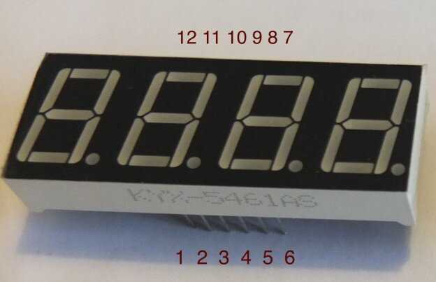
The physical terminals 6, 8, 9 and 12 must be connected to GND of the ARDUINO board. We'll see further how to proceed, because these four terminals must be managed in a particular way through a specific port.
We will first wire these four physical terminals as follows:
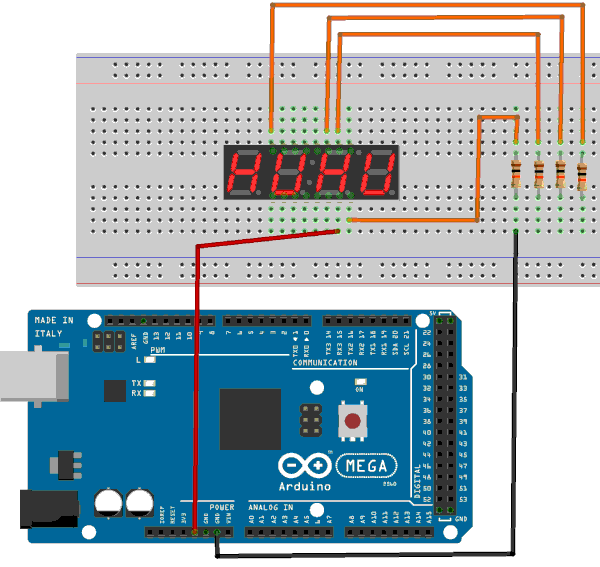
Turn on the ARDUINO MEGA card. One of the segments of the display should light up. You can move the red wire to the other connectors and verify that all segments of the display are operational. If you move the black wire on the board to the right, on the next resistor, you go at the second digit.
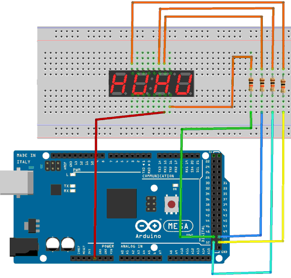
Connecting the cathodes 6, 8, 9 and 12 to the ARDUINO board
We will connect the physical terminals 6, 8, 9 and 12 of the 4x7 segment display as follows:
PB0 -> pin 19 -> connector 53 -> pin 6
PB1 -> pin 20 -> connector 52 -> pin 8
PB2 -> pin 21 -> connector 51 -> pin 9
PB3 -> pin 22 -> connector 50 -> pin 12
Connection diagram:
We will now check that this wiring is correct. We define, in FORTH:
\ PORT B
37 constant PORTB
36 constant DDRB
35 constant PINB
: initDDRB ( c DDR ---)
    $ff DDRB c!   \ set all PORT B bits in output mode
    ;
We execute:
initDDRB
%00000000 PORTB c!   \ met tous les PIN du PORT B à l'état bas
If you have left the red wire connected to the 5V on the ARDUINO board and on a inputs of the 7-segment display, you should see the same segment on the 4 digits. We will extinguish the rightmost figure:
%00000001 PORTB c!
Setting the low-order bit to 1 turns off the first segment!
%00000010 PORTB c!
Setting the second bit to 1 turns off the second segment.
The logic of digital pins on ARDUINO cards
On ARDUINO cards, there are two kinds of pins:
- digital pins
- analog pins
The digital pins are activated as inputs (to manage a push button for example), or in outputs to emit an "all" or "nothing" signal:
- all = 5V, level hight
- nothing = 0V, level down
The low state is related to the mass (GND). The high state delivers a voltage of 5V.
You can turn off all digits of the display like this:
%00001111 PORTB c!
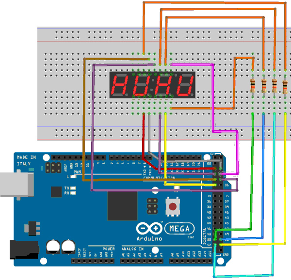
Connecting the other terminals of the 4x7 segment display
Voic les connexions à réaliser sur le PORT A:
PA0 -> pin 76 -> connecteur 24 -> borne 1 -> segment E
PA1 -> pin 75 -> connecteur 25 -> borne 2 -> segment D
PA2 -> pin 74 -> connecteur 26 -> borne 4 -> segment C
PA3 -> pin 73 -> connecteur 27 -> borne 7 -> segment B
PA4 -> pin 72 -> connecteur 28 -> borne 11 -> segment A
PA5 -> pin 71 -> connecteur 29 -> borne 10 -> segment F
PA6 -> pin 70 -> connecteur 30 -> borne 5 -> segment G
Caution: do not confuse physical connector numbers and pin numbers
On the ARDUINO cards, the physical connectors are marked, some by numbers, others by their function, example: GND, TX, RX, 5V, etc ...
The mapping for associating pin numbers with physical connectors is in this document:
Pin out map on ARDUINO DUE
Pin out map on ARDUINO MEGA 2560
Pin out map on ARDUINO MICRO
Pin out map on ARDUINO NANO
Pin out map on ARDUINO UNO
Pin out map on ARDUINO YUN
For example, the led '13' which is connected to the ARDUINO MEGA board with the physical terminal 13 is related to the PIN 26. In all our texts, the term "pin" will always refer to PIN code XX as referenced in the technical documents of ARDUINO cards. The mention of a physical connector will be done with the term 'terminal'. Example:
PIN 19 (terminal 53) (penultimate terminal, all at the bottom, left on an ARDUINO MEGA 2560 board)
To learn more about how to program the connectors of the different ARDUINO boards:
Understanding ARDUINO card connectors
| chiffre | --- -- |
PA6 G |
PA5 F |
PA4 A |
PA3 B |
PA2 C |
PA1 D |
PA0 E |
|---|---|---|---|---|---|---|---|---|
| 0 | 0 | 0 | 1 | 1 | 1 | 1 | 1 | 1 |
| 1 | 0 | 0 | 0 | 0 | 1 | 1 | 0 | 0 |
| 2 | 0 | 1 | 0 | 1 | 1 | 0 | 1 | 1 |
| 3 | 0 | 1 | 0 | 1 | 1 | 1 | 1 | 0 |
| 4 | 0 | 1 | 1 | 0 | 1 | 1 | 0 | 0 |
| 5 | 0 | 1 | 1 | 1 | 0 | 1 | 1 | 0 |
| 6 | 0 | 1 | 1 | 1 | 0 | 1 | 1 | 1 |
| 7 | 0 | 0 | 0 | 1 | 1 | 1 | 0 | 0 |
| 8 | 0 | 1 | 1 | 1 | 1 | 1 | 1 | 1 |
| 9 | 0 | 1 | 1 | 1 | 1 | 1 | 1 | 0 |
Only the decimal point is not wired:
FORTH multiplexing
We will now define the parameters of PORT A and the matrix bitmap to handle segments representing numbers:
Notice: Undefined variable: ff in /home/arduinofom/www/articles/pages/FORTH/FlashForth/gestionAfficheur4x7segments.phtml on line 293
\ PORT A
34 constant PORTA	\ Port A Data Register
33 constant DDRA	\ Port A Data Direction Register
32 constant PINA	\ Port A Input Pins
: initDDRA ( c DDR ---)
     DDRA c!   \ set all PORT A bits in output mode
    ;
create digits  ( --- addr)
    %00111111 c,    \ digit 0
    %00001100 c,    \ digit 1
    %01011011 c,    \ digit 2
    %01011110 c,    \ digit 3
    %01101100 c,    \ digit 4
    %01110110 c,    \ digit 5
    %01110111 c,    \ digit 6
    %00011100 c,    \ digit 7
    %01111111 c,    \ digit 8
    %01111110 c,    \ digit 9
    %00000000 c,    \ display off
: >7seg ( n ---)
    digits +        \ increase addr with value n
    c@              \ fetch c that will be send to 7 segments display
    PORTA c! ;      \ send value to display
The 3 >7seg sequence displays 3 on the 7-segment display.
The word >7seg can only be preceded by a value between 0 and 9. Any other
value will cause a random effect...
End of the code managing the 4x7 segment display:
5 constant DELAY    \ time to display 1 digit before next digit

ram
create valToDisp    \ 4 bytes array
    4 allot         \ for 4 digits to display

flash
: displayLoop ( ---)
    begin
        valToDisp 0 + c@ >7seg
        %00001110 PORTB c! DELAY ms
        valToDisp 1 + c@ >7seg
        %00001101 PORTB c! DELAY ms
        valToDisp 2 + c@ >7seg
        %00001011 PORTB c! DELAY ms
        valToDisp 3 + c@ >7seg
        %00000111 PORTB c! DELAY ms
    key? until
    $ff PORTB c! ;

: nDisp ( n ---)    \ display value n on 4 x 7 segments
    0               \ convert n to d
    4 for
        10 ud/mod   \ leave modulo and quotient in double integer
    next
    2drop           \ drop rest of quotient
    4 for
        valToDisp   \ store each digit in array valToDisp
        r@ + c!
    next
    displayLoop     \ display content of valToDisp
 ;
The word displayLoop has been deliberately unoptimized to remain
understandable. Its definition takes each successive byte contained in the variable
valToDisplay and inject this byte into port A via the word >7seg.
For each digit, one segment is active at a time. 5 milliseconds delay
is defined in the DELAY constant. Too big a value causes a
flickering effect.
The word nDisp displays any value between 0 and 9999 on four digits.
The value n is converted to a double precision value. Then in the first loop
for..next, the sequence 10 ud/mod leaves on the stack the quotient
and the rest of the division of this value divided by 10. Example, treat 1972:
1972  ok<#,ram> 1972
0  ok<#,ram> 1972 0
10 ud/mod  ok<#,ram> 2 197 0
10 ud/mod  ok<#,ram> 2 7 19 0
10 ud/mod  ok<#,ram> 2 7 9 1 0
10 ud/mod  ok<#,ram> 2 7 9 1 0 0
2drop  ok<#,ram> 2 7 9 1
The second loop for..next in the word nDisp stores
byte byte the values thus decomposed in the variable valToDisp.
valToDisp is actually an array of 4 bytes. It's as simple as that.
Finally, we launch the display of the injected value to nDisp which executes
displayLoop
1234 nDisp  \ affiche 1234 sur afficheur 4x7 segments
7654 nDisp  \ affiche 7654 sur afficheur 4x7 segments
55 nDisp    \ affiche 0055 ...