ARDUINO ports: Management of a 7-segment display
published: 8 June 2019 / updated 11 June 2019

We had already treated an example of simultaneous pine management in the article entitled ARDUINO ports: K2000 maze.
In this article, we will in particular unfold the so-called development method: bottom-up, the so-called bottom-up approach. This method goes into detail to build the tools for optimal component management.
The 7-segment display
Here are the features of the 7-segment display. This component has 10 terminals physical, numbered from 1 to 10:
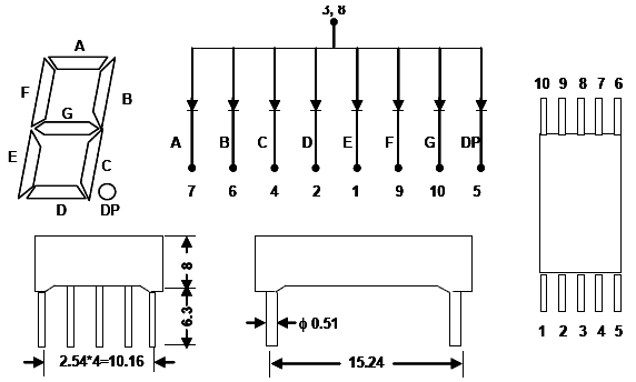
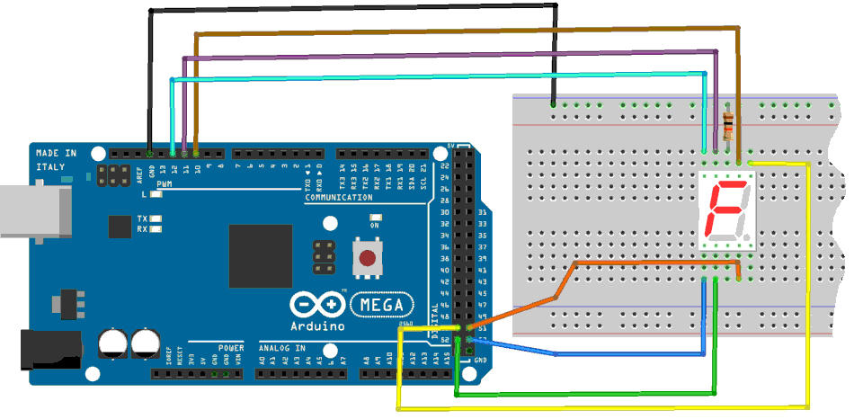
On this data sheet, the decimal point is marked DP. This point must be located on the bottom right so that the 7 segment display is correctly oriented. Terminals 3 and 8 correspond to the common cathode. Place the display on the test plate and connect terminal 8 to ground via a resistor of approximately 300 Ohms. Diagram:
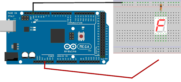
Temporarily insert a jumper wire to the 5V of the ARDUINO board (red wire on the diagram). With the other end of this wire, test connectors 1, 2, 4, 5, 6, 7 9 and 10. If all goes well, each segment must light according to the technical data of the 7-segment display.
We have just successfully crossed the very first stage of our development process, called bottom-up. In this process, we understood and mastered the functioning of a component, here the 7-segment display.
PORT B in detail
Still in this same bottom-up approach, we will now see in detail
the physical connection of PORT B. On the ARDUINO MEGA 2560 board, it is a port that manages eight pins,
numbered 19 to 26. For the MEGA 2560, the numbering of these pins is described here:
Pin out map on ARDUINO MEGA 2560.
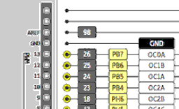
Here is the detail of the pins 19 to 23 which are managed in the lower left part on the MEGA 2560 card:
In yellow, the bit number in port B: PB0 = Port B bit 0, PB1 = Port B bit 1, etc. Bit numbering
always starts at zero. In gray, opposite the bit number p in the port, the pin number: PB0 -> pin 19, PB1 -> pin 20.
For each pin 19 to 22, the physical connector number on the ARDUNO MEGA board:
PB0 -> pin 19 -> connector 53
PB1 -> pin 20 -> connector 52
PB2 -> pin 21 -> connector 51
PB3 -> pin 22 -> connector 50
...Ah! But where are bits 4 to 7 of port B?
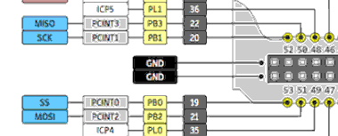
Bits 4 to 7 of Port B are on the upper right side of the MEGA 2560 board:
For each pin 23 to 26, the physical connector number on the ARDUNO board:
PB4 -> pin 23 -> connector 10
PB5 -> pin 24 -> connector 11
PB6 -> pin 25 -> connector 12
PB7 -> pin 26 -> connector 13
...Ah yes! So the bits of PORT B are in two different places!
Caution: do not confuse physical connector numbers and pin numbers
On the ARDUINO cards, the physical connectors are marked, some by numbers, others by their function, example: GND, TX, RX, 5V, etc ...
The mapping for associating pin numbers with physical connectors is in this document:
Pin out map on ARDUINO DUE
Pin out map on ARDUINO MEGA 2560
Pin out map on ARDUINO MICRO
Pin out map on ARDUINO NANO
Pin out map on ARDUINO UNO
Pin out map on ARDUINO YUN
For example, the led '13' which is connected to the ARDUINO MEGA board with the physical terminal 13 is related to the PIN 26. In all our texts, the term "pin" will always refer to PIN code XX as referenced in the technical documents of ARDUINO cards. The mention of a physical connector will be done with the term 'terminal'. Example:
PIN 19 (terminal 53) (penultimate terminal, all at the bottom, left on an ARDUINO MEGA 2560 board)
To learn more about how to program the connectors of the different ARDUINO boards:
Understanding ARDUINO card connectors
In FORTH, we will create the words necessary and sufficient to manage this port B:
37 constant PORTB
36 constant DDRB
\ 35 constant PINB
The word PORTB is the address of the PORTB register. It's in this register
that we will inject the binary value to turn on the segments of the 7-segment display.
The word DDRB corresponds to the address of the DDR register of port B. In this register, we will
indicate the meaning of the data handled by PORT B:
: initDDRB ( ---)
    %11111111 DDRB c!   \ positionne tous bits PORTB en sortie
    ;
Wiring the 7-segment display
This is the most delicate part of managing the 7-segment display. We go initialize the DDRB register and activate the bits of port B:
initDDRB
%11111111 PORTB c!
We must physically connect our display as follows. Gradually as
the connectors of the ARDUINO card are physically connected to those
of the 7-segment display, each segment of light will come on if you meet
scrupulously these connections:
PB0 -> pin 19 -> connector 53 -> terminal 1 -> segment E
PB1 -> pin 20 -> connector 52 -> terminal 2 -> segment D
PB2 -> pin 21 -> connector 51 -> terminal 4 -> segment C
PB3 -> pin 22 -> connector 50 -> terminal 6 -> segment B
PB4 -> pin 23 -> connector 10 -> terminal 7 -> segment A
PB5 -> pin 24 -> connector 11 -> terminal 9 -> segment F
PB6 -> pin 25 -> connector 12 -> terminal 10 -> segment G
PB7 -> pin 26 -> connector 13 -> terminal 5 -> segment DP
Each segment should light up as you go up physical connections between the ARDUINO board and the 7 segment display:
Display of digits 0 to 9
Our segments of the 7 segment display are all wired to the ARDUINO board. Let's now how to display numbers. For that, we will define this table:
| chiffre | PB7 DP |
PB6 G |
PB5 F |
PB4 A |
PB3 B |
PB2 C |
PB1 D |
PB0 E |
|---|---|---|---|---|---|---|---|---|
| 0 | 0 | 0 | 1 | 1 | 1 | 1 | 1 | 1 |
| 1 | 0 | 0 | 0 | 0 | 1 | 1 | 0 | 0 |
| 2 | 0 | 1 | 0 | 1 | 1 | 0 | 1 | 1 |
| 3 | 0 | 1 | 0 | 1 | 1 | 1 | 1 | 0 |
| 4 | 0 | 1 | 1 | 0 | 1 | 1 | 0 | 0 |
| 5 | 0 | 1 | 1 | 1 | 0 | 1 | 1 | 0 |
| 6 | 0 | 1 | 1 | 1 | 0 | 1 | 1 | 1 |
| 7 | 0 | 0 | 0 | 1 | 1 | 1 | 0 | 0 |
| 8 | 0 | 1 | 1 | 1 | 1 | 1 | 1 | 1 |
| 9 | 0 | 1 | 1 | 1 | 1 | 1 | 1 | 0 |
At the beginning of the line, the number to display. Then, the values 0 or 1 for each segment to activate. On the first line of the digit 0 to display, the eight bits PB0 through PB7 to activate. These bits can be tested immediately by grouping them into a single binary value:
%00111111 PORTB c!
The 7-segment display should show the number 0. The display will be off:
$00 PORTB c!
To display numbers from 0 to 9:
: testDigits  ( ---)
    %00111111 PORTB c! 500 ms   \ affiche 0
    %00001100 PORTB c! 500 ms   \ affiche 1
    %01011011 PORTB c! 500 ms   \ affiche 2
    %01011110 PORTB c! 500 ms   \ affiche 3
    %01101100 PORTB c! 500 ms   \ affiche 4
    %01110110 PORTB c! 500 ms   \ affiche 5
    %01110111 PORTB c! 500 ms   \ affiche 6
    %00011100 PORTB c! 500 ms   \ affiche 7
    %01111111 PORTB c! 500 ms   \ affiche 8
    %01111110 PORTB c! 500 ms   \ affiche 9
    $00 PORTB c! ;              \ éteint afficheur
Here, it's just a display test that allows us to check that our numbers are displayed correctly on our 7 segment display. Ideally now to have a word that stores these 10 binary values in a table:
flash
create digits  ( --- addr)
    %00111111 c,    \ chiffre 0
    %00001100 c,    \ chiffre 1
    %01011011 c,    \ chiffre 2
    %01011110 c,    \ chiffre 3
    %01101100 c,    \ chiffre 4
    %01110110 c,    \ chiffre 5
    %01110111 c,    \ chiffre 6
    %00011100 c,    \ chiffre 7
    %01111111 c,    \ chiffre 8
    %01111110 c,    \ chiffre 9
    %00000000 c,    \ éteint afficheur
The word create is a FORTH creation word. It is followed by the word to create, here digits.
Then, each line compiles each byte to display a number on the 7-segment display.
Execution of the word digit sets the memory address of the first digit for the 7-segment display:
digits c@ PORTB c! \ affiche le chiffre 0
To display another digit, simply increment the address issued by digits
the desired number of bytes before extracting the value to be injected into the 7-segment display. Example,
to display the number 4 on the 7 segment display:
digits 4 + c@ PORTB c! \ affiche le chiffre 0
Let's define a word that will factor this:
: >7seg ( n ---)
    digits +        \ incrémente adresse valeur n
    c@              \ récupère c à envoyer à afficheur 7 segments
    PORTB c! ;      \ envoie valeur à l'afficheur
The 3 >7seg sequence displays 3 on the 7-segment display.
The word >7seg can only be preceded by a value between 0 and 9. Any other
value will cause a random effect...
If you want to display the numbers A to F for hexadecimal coding, we leave you to the care to extend the code for these extra digits .... Hey yes! In hexadecimal encoding, A to F are numbers ...
An ARDUINO chase
The ARDUINO logo is the infinite symbol, a coated 8. We will generate a chase that draws this "8" on our 7 segment display:
flash
create chenille   ( --- addr)
%00000110 c,
%01000100 c,
%01100000 c,
%00110000 c,
%00011000 c,
%01001000 c,
%01000001 c,
%00000011 c,
: boucle-chenille ( ---)
    begin
        8 for
          8 r@ - 1-     \ calcul index qui doit aller de 0 à 7
          chenille + c@ \ récupère octet à envoyer à afficheur 7 segments
          PORTB c!      \ envoi octet vers afficheur 7 segments
          100 ms        \ attente 0,1 sec
        next
    key?                \ ai ppui touche, sort de la boucle begin..until
    until ;
The segments are lit two by two, following an "8" path...
Dice game
By just taking the few elements already developed, we will create a game of drawing dice.
We define a random function rand that outputs a random number:
\ *** jeu de dés ***********
variable rnd \ holds some entropy
\ get a random number
: random ( -- n )
    rnd @  31421 *  6927 +  dup rnd !
;
\ get a random number between 0 and u
: rand ( u -- 0..u-1)
    random um* nip
;
\ rand sort un nombre aléatoire enre 0 et u-1
This word rand is then used to make a draw
in the word sortDe:
: sortDe ( --- n)
 6 rand 1+ ;        \ tirage aléatoire entre 1 et 6
And for it to be more sexy, we create the word tirageDe:
: tirageDe ( ---)
    4 for
        8 for
          8 r@ - 1-     \ calcul index qui doit aller de 0 à 7
          chenille + c@ \ récupère octet à envoyer à afficheur 7 segments
          PORTB c!      \ envoi octet vers afficheur 7 segments
          100 ms        \ attente 0,1 sec
        next
    next
    sortDe >7seg
    ;
The word tirageDe throws an Arduino chaser (see above), then
extracts a random value and envy to the 7-segment display.
Conclusion
We are here at the last stage of the bottom-up development process because the end has been reached: a dice game to illustrate the management of a 7-segment display.
We hope you understand the process of this development process:
- understand the component to manage
- mount the tools to handle this component
- use these tools
FORTH does not pretend to be better than this or that other development language. FORTH is simply an alternative. Through this example, you have seen that it is easy to master a bottom-up development process.