Hacking an infrared remote control
published: 29 April 2024 / updated 29 April 2024

article: 04 juil. 2019 / mis à jour 12 juil. 2019
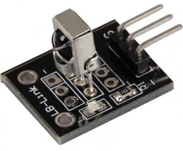
The infrared receiver KY-O22
It is a receiver with three connectors:
And here's how to connect this receiver to an ARDUINO Mega board:
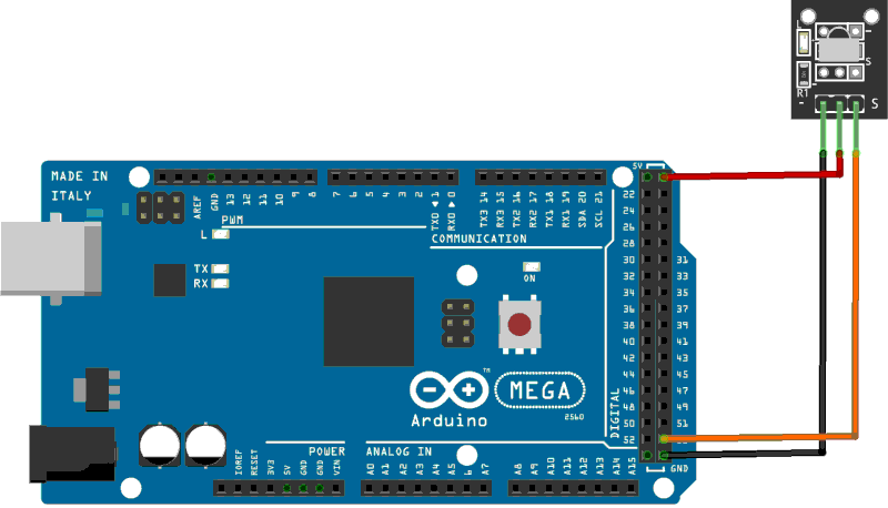
Wiring:
- black wire: to mass of the ARDUINO Mega board
- red wire: to power + 5V of the ARDUINO Mega board
- orange wire: to PB0 connector (pin 19) physical connector 53
Caution: do not confuse physical connector numbers and pin numbers
On the ARDUINO cards, the physical connectors are marked, some by numbers, others by their function, example: GND, TX, RX, 5V, etc ...
The mapping for associating pin numbers with physical connectors is in this document:
Pin out map on ARDUINO DUE
Pin out map on ARDUINO MEGA 2560
Pin out map on ARDUINO MICRO
Pin out map on ARDUINO NANO
Pin out map on ARDUINO UNO
Pin out map on ARDUINO YUN
For example, the led '13' which is connected to the ARDUINO MEGA board with the physical terminal 13 is related to the PIN 26. In all our texts, the term "pin" will always refer to PIN code XX as referenced in the technical documents of ARDUINO cards. The mention of a physical connector will be done with the term 'terminal'. Example:
PIN 19 (terminal 53) (penultimate terminal, all at the bottom, left on an ARDUINO MEGA 2560 board)
To learn more about how to program the connectors of the different ARDUINO boards:
Understanding ARDUINO card connectors
The words defPIN: high low output input and pin@ are described
in the article Definition and management of PORT connections
Infrared receiver test
The ARDUINO card is turned on. We take an infrared remote control. We lead her to this infrared receiver. You press a button on the remote control. If all goes well, a red control led flashes on the KY-022 receiver.
Here's the physical part. Let's move on to the computer part. PORT B is prepared:
37 constant PORTB    \ define register PORT port B
36 constant DDRB     \ define register DDR  port B
35 constant PINB     \ define register PIN  port B

%00000001 constant pin19    \ mask 00000001 for pin 19 (PB0)
%10000000 constant pin26    \ mask 10000000 for pin 26 (PB7)

: init-ddrb ( ---)
    pin19 DDRB mclr         \ init PORTB to input for PB0
    pin26 DDRB mset         \ init PORTB to output for PB7
  ;
Pins 19 and 26 are managed. Pin 19 (PB0) is the one on which we receive signals received by the KY-022 receiver. Pin 26 (PB7) is the one on which we find the led soldered to the ARDUINO board in connection with pin 26 (physical connector 13).
Retrieving the signal from the remote control by interruption
To recover the signal from the remote control, we will mount an interruption. Firstly, the received signal will simply switch the state of the control LED:
: ledDelay ( n ---)
    for next
    ;
: toggleLed ( ---)
    %00000001 PCMSK0 mclr   \ mask interrupt for PB0
    pin26 PORTB mtst
    if      pin26 PORTB mclr
    else    pin26 PORTB mset
    then
    %00000001 PCMSK0 mset   \ enable interrupt for PB0
    ;i
Then we initialize the interruption:
\ ATTENTION: spécifique Mega 2560
10 constant PCINT0          \ External Interrupt Request 4

$6b constant PCMSK0         \ Pin Change Mask Register 0
104 constant PCICR          \ Pin Change Interrupt Control Register $68

: init-tgLed
    ['] toggleLed PCINT0 int!
    %00000001 PCMSK0 mset \ mask interrupt for PB0
    %00000111 PCICR  mset
    ei                    \ ei = Enable Interrupt
;

init-tgLed
init-ddrb
And now, if you press on the remote control, the control LED of the receiver KY-022 flashes, but also the ARDUINO Mega card:
Listing de cette partie ici:
Analyze the infrared flow
Now that we know how to act by means of a material interruption when the infrared receiver receives a signal, let's see how to store this signal.
Sampling the signal from the IR remote control
Our approach is to go step by step. At each stage, it happens that the tests lead to dead ends. The following explanations do not take consider these impasses.
When the infrared receiver receives a signal from the remote control, it flashes briefly several times. We can therefore assume that the connector PB0 (pin 19) on our ARDUINO Mega board receives a succession of 0 and 1 (low and high electrical state). Since we do not have of oscilloscope to analyze this signal looked up by the infrared receiver KY-022, we will make a little routine to sample that signal
We define:
1000 constant MAXPULSE      \ max units sampling
ram  variable resolution    \ delay between two sampling
    410 resolution !        \ estimated value....

ram create samplings        \ store samplings
    MAXPULSE allot
The MAXPULSE constant indicates the maximum number of samples that we
let's analyze.
The resolution variable is used to adjust the interval between two samples.
The samplings array is responsible for storing samples.
The word irState@ is responsible for recovering the state of the signal received by the infrared receiver KY-022
and transmitted on PB0:
: irState@ ( --- 0|1)       \ infrared state
    pin19 PINB mtst         \ pin 19 = PBO for Arduino MEGA 2560
    ;
The wordtgLed is responsible for changing the state of the LED that is on the
ARDUINO card and in connection with PB7 (pin 26).
: tgLed ( ---)              \ toggle LED on PB7 (Arduino MEGA)
    pin26 PORTB mtst
    if      pin26 PORTB mclr
    else    pin26 PORTB mset
    then
    ;
The word tgLed tests whether the led is on. If so, it turns off the LED. Yes
the LED is off, it turns it on.< p>
And here is our sampling loop:
: getIrStream ( ---)
    %00000001 PCMSK0 mclr
    samplings 1-    \ decrement samplings addr
    MAXPULSE for
        1+          \ increment samplings addr
        irState@ over c!
        resolution @ us  \ delay in µseconds
    next
    drop
    tgLed
    ." >"
    1000 us
    %00000001 PCMSK0 mset
    ;i

: init-irStream
    ['] getIrStream PCINT0 int!
    %00000001 PCMSK0 mset \ mask interrupt for PB0
    %00000001 PCICR  mset
    ei                    \ ei = Enable Interrupt
    ;

init-irStream
init-ddrb
The word getIrStream can not be executed directly. It is
interrupted as soon as an infrared signal is received by the receiver
KY-022 and transmitted on the PB0 terminal.
The definition of getIrStream begins with %00000001 PCMSK0 mclr.
This line is used to inhibit all interrupt requests.
Next, the MAXPULSE for ... next loop performs the sampling
states of the infrared signal transis via the KY-022 receiver.
After this loop, we find this: tgLed ." >" 1000 us. This part of code
only for the development phase.
Sample processing
At this stage of development of our program, we can already test the good reception
infra-red signal from the remote control. If the interrupt was correctly initialized by
the word init-irStream, the LED that is on the ARDUINO board should turn on or off
each time you press the remote control. In addition, side display in the terminal, must appear the character ">"
which materializes the good execution of the interruption.
We can dump the contents of the array samplings:
hex samplings ¤ff dump
04e4 :00 00 00 00 00 00 00 00 00 00 00 00 00 00 00 00 ................
04f4 :00 00 00 00 00 00 01 01 01 01 01 01 01 01 01 01 ................
0504 :01 00 01 00 00 01 00 00 01 00 01 00 00 01 00 00 ................
0514 :01 00 01 01 00 01 00 00 01 01 01 01 00 01 01 01 ................
0524 :01 00 01 01 01 01 00 00 01 01 01 01 00 01 01 01 ................
0534 :01 00 01 01 01 01 00 00 01 01 01 00 00 01 01 01 ................
0544 :01 00 01 01 00 01 00 00 01 01 01 01 00 01 01 01 ................
0554 :01 00 01 01 00 01 00 00 01 00 01 01 00 01 01 01 ................
But as this display is not explicit enough, we define this word disp.samples:
: disp.samples ( ---)
    cr
    samplings 1-
    MAXPULSE for
        dup c@ 0=
        if
            ." ."
        else
            ." X"
        then
        1+
    next
    drop
    ;
This word will "replace" our oscilloscope. All "00" values will be displayed in the form of "." and the values "01" in the form of "X". Result:
disp.samples
X......................XXXXXXXXXXX.X..X..X.X..X..X.XX.X..XXXX.XXXX.XXXX..XXXX.XX
XX.XXXX..XXX..XXXX.XX.X..XXXX.XXXX.XX.X..X.XX.XXXX.XXXX..X.XX.XXXX.XXXX..XXXX.XX
XX.XXXXXXXXXXXXXXXXXXXXXXXXXXXXXXXXXXXXXXXXXXXXXXXXXXXXXXXXXXXXXXXXXXXXXXXXXXXXX
XXXXXXXXXXXXXXXXXX......................XXXXX..XXXXXXXXXXXXXXXXXXXXXXXXXXXXXXXXX
XXXXXXXXXXXXXXXXXXXXXXXXXXXXXXXXXXXXXXXXXXXXXXXXXXXXXXXXXXXXXXXXXXXXXXXXXXXXXXXX
XXXXXXXXXXXXXXXXXXXXXXXXXXXXXXXXXXXXXXXXXXXXXXXXXXXXXXXXXXXXXXXXXXXXXXXXXXXXXXXX
You can adjust the value of the variable resolution and repeat several tests.
The lower the content of the resolution, the more the interruption
performs sampling.
Translation in progress
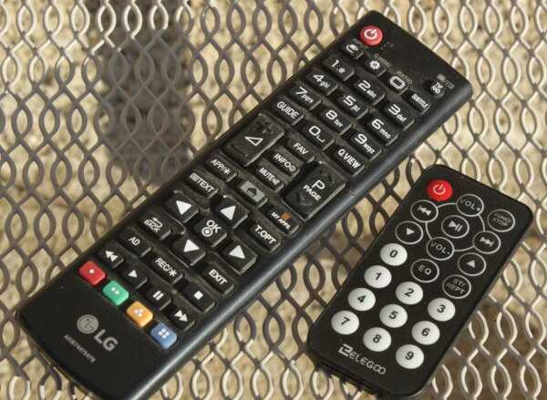
Résultat de tests avec différentes télécommandes infrarouge
Nous avons réalisé plusieurs test de réception de codes avec deux télécommandes:
- la télécommande eelego fournie avec le kit de développement ARDUINO MEGA;
- une télécommande TV de marque LG.
L'interruption matérielle récupère les codes transmis par ces deux télécommandes.
Pour une même touche activée, par exemple la touche "1", les codes transmis par ces deux télécommandes sont différents. L'idée est de rendre la trame binaire plus lisible.
Quasiment toutes les télécommandes infrarouge des appareils domestiques utilisent la norme RC5. En savoir plus RC5 (protocole) (Wikipedia).
Nous n'avons pas souhaité réaliser le décodage de la norme CR5. D'une part, c'est assez complexe à réaliser. D'autre part, ça n'apporte rien pour une application pratique.
Voici un mot qui réalise une analyse plus compacte que celle du mot disp.samples:
\ display byte in hex format
: #hh ( n --- str)
    base @ >r
    hex
    0 <# # # #>
    r> base !
    ;
\ display input values received in samplings
ram variable valDecode
: disp.values ( ---)
    cr
    samplings 1-
    MAXPULSE 8 / for
        0 valDecode !
        8 for
            valDecode @ 2* valDecode !  \ left shift
            dup c@ 1 =
            if
                1 valDecode +!
            then
            1+      \ increment pointer in samplings
        next
    valDecode @ #hh type
    next
    drop
    ;
Voici le résultat d'une trame visualisée avec disp.values:
disp.values
800001ffd2d25273de73de73d273d25bde5bde7bdfffffffffffffffffffffffffffffffffffffff
ok<$,ram>
Chaque paire de caractères correspond à un octet reconstitué bit à bit à partir de la séquence de "0" et de "1" récupérés lors de notre échantillonnage.
La première moitié de la séquence ainsi décodée montre une variation du contenu. La seconde moitié montre que l'échantillonnage est statique.
Le résultat affiché par disp.values n'est pas satisfaisant. Il est trop long. Il faut trouver
une astuce pour générer un résultat court et facile à exploiter.
Compression par CRC 16
L'algorithme de contrôle de redondance cyclique (Cyclic Redundancy Check) nous semble le noyen le plus facile pour générer un code 16 bits unique réalisé à partir du résultat de notre échantillonage:
Notice: Undefined variable: a001 in /home/arduinofom/www/articles/pages/FORTH/FlashForth/hackTelecommandeInfraRouge.phtml on line 480
: crc-16 ( crc byt -- crc' )
    xor
    8 for
        dup
        1 and
        if
            1 rshift
             xor
        else
            1 rshift
        then
    next
    ;