The SPI interface: management of an 8x8 LEDS display
published: 19 June 2019 / updated 24 November 2019

We saw in the article entitled ARDUINO ports: Managing a 4 x 7 segment display how to manage, in FORTH language, several 7 segment displays by multiplexing. The disadvantage of this method is that it requires the permanent exploitation of the resources of the microcontroller on the map ARDUINO.
By learning how to manage the display on an 8x8 LED matrix, through the MAX7219 multiplexer, you can release the resources of the micro-controller.
The 8x8 LED matrix
Find all the features of the matrix MAX7219 8x8 LEDs here:
The SPI interface
To communicate between the ARDUINO board and the 8x8 LED display managed by the MAX7219 chip, it must transmit the information via the SPI interface.
The program used is inspired by the one developed by P. A. Jacobs and available here: Drive MAX7219 display chip 8x8 LED matrix.
But as the tests were made from an ARDUINO MEGA 2560 board, it was necessary to make some modifications.
Find the connectors of the SPI interface
Before connecting the 8x8 LED display, the corresponding pins must be found on the ARDUINO board.
You will find the connector card from ARDUINO UNO here: Pin out map on ARDUINO UNO
Here is the part that interests us:
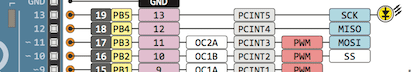
On this extract of the connector board, from left to right, from the bottom:
- 10 -> PB2 -> 10 -> OC1B -> PCINT2 -> PWM -> SS
On the left, the physical connector number on the ARDUINO UNO board.
This number, here 10 is followed by B2 which means that this connector is in direct connection with bit 2 on PORT B. As a reminder, the numbering of the bits of a port goes from 0 to 7. That's why we find this in the FORTH code:
%00000100 constant mSS1 ( PB2 )
Starting from the right, bit 0 to 0, bit 1 to 0, bit 2 to 1 ... The remaining bits remain at 0. Hence the binary value %000100 in the FORTH code.
In summary, here is the order and meaning of the connectors related to the SPI port on the ARDUINO UNO card:
- 10 -> PB2 -> ... SS (Slave Select)
- 11 -> PB3 -> ... MOSI (Master Output, Slave Input)
- 12 -> PB4 -> ... MISO (Master Input, Slave Output)
- 13 -> PB5 -> ... SCK (Serial Clock)
For the ARDUINO MEGA 2560 board, the SPI interface connectors are located elsewhere. Here the connector card from the MEGA ARDUINO: Pin out map on ARDUINO MEGA 2560
Here is the part that interests us:
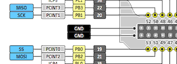
Here is the order and meaning of the connectors related to the SPI port on the ARDUINO MEGA card:
- 53 -> PB0 -> ... SS (Slave Select)
- 51 -> PB2 -> ... MOSI (Master Output, Slave Input)
- 50 -> PB3 -> ... MISO (Master Input, Slave Output)
- 52 -> PB1 -> ... SCK (Serial Clock)
Caution: do not confuse physical connector numbers and pin numbers
On the ARDUINO cards, the physical connectors are marked, some by numbers, others by their function, example: GND, TX, RX, 5V, etc ...
The mapping for associating pin numbers with physical connectors is in this document:
Pin out map on ARDUINO DUE
Pin out map on ARDUINO MEGA 2560
Pin out map on ARDUINO MICRO
Pin out map on ARDUINO NANO
Pin out map on ARDUINO UNO
Pin out map on ARDUINO YUN
For example, the led '13' which is connected to the ARDUINO MEGA board with the physical terminal 13 is related to the PIN 26. In all our texts, the term "pin" will always refer to PIN code XX as referenced in the technical documents of ARDUINO cards. The mention of a physical connector will be done with the term 'terminal'. Example:
PIN 19 (terminal 53) (penultimate terminal, all at the bottom, left on an ARDUINO MEGA 2560 board)
To learn more about how to program the connectors of the different ARDUINO boards:
Understanding ARDUINO card connectors
Programming the SPI interface
Find complete explanations on the programming of the SPI interface here:
The SPI interface of ARDUINO boards
Find the complete listing of the programming of this SPI interface here:
Words to drive the SPI module on the ATmega2560
Programming the 8x8 LEDs display
The program used is inspired by the one developed by P. A. Jacobs and available here: Drive a MAX7219 display chip with 8x8 LED matrix. (source: A Tutorial Guide to Programming PIC18, PIC24 and ATmega Microcontrollers with FlashForth. 2016 Revision).
Here is the word that will communicate with the MAX7219 chip:
: max7219.send ( c1 c2 -- )
    mSS1 slave.select
    swap spi.csend spi.csend
    mSS1 slave.deselect
  ;
Parameters c1 and c2 correspond to:
- c1 address in the MAX7219 chip register. Values from $ 00 to $ 0f.
- c2 value in the MAX7219 chip register. Values between $ 00 and $ ff.
The order of these parameters appears to match those of the max.send() function.
in C language. The max.send() function in C language accepts three parameters, the
first being the selection of the MAX7219 chip. The word max7219.send only takes over
the last two parameters, the selection of the chipMAX7219 being realized by the word slave.select,
word that that requires the mask mSSx (MSS1 in our case) as a parameter.
Meaning of addresses c1:
| adr | signification |
|---|---|
| $00 | No-Op |
| $01 | Digit 0 |
| $02 | Digit 1 |
| $03 | Digit 2 |
| $04 | Digit 3 |
| $05 | Digit 4 |
| $06 | Digit 5 |
| $07 | Digit 6 |
| $08 | Digit 7 |
| $09 | Decode Mode |
| $0a | Intensity |
| $0b | Scan Limit |
| $0c | Shutdown |
| $0d | --unused-- |
| $0e | --unused-- |
| $0f | Display Test |
These different addresses are exploited in these words:
: disp.normal ( -- )
    $0c $01 max7219.send ;
: disp.shutdown ( -- )
    $0c $00 max7219.send ;
: disp.test.on ( -- )
    $0f $01 max7219.send ;
: disp.test.off ( -- )
    $0f $00 max7219.send ;
: disp.no.op ( -- )
    $00 $00 max7219.send ;
: disp.intensity ( c -- )
    $0a swap max7219.send ;
: disp.decode ( c -- )
    $09 swap max7219.send ;
: disp.scan.limit ( c -- )
    $0b swap max7219.send ;
: disp.set.digit ( cbits cdigit -- )
    swap max7219.send ;
The word that interests us the most is disp.set.digit, word exploited
in disp-test-3:
: disp-test-3 ( -- ) \ draw face, 18mA needed
    spi.init
    disp.normal
    $01 disp.intensity
    $07 disp.scan.limit
    %00000000 $01 disp.set.digit
    %01100110 $02 disp.set.digit
    %00000000 $03 disp.set.digit
    %00011000 $04 disp.set.digit
    %00011000 $05 disp.set.digit
    %10000001 $06 disp.set.digit
    %01000010 $07 disp.set.digit
    %00111100 $08 disp.set.digit
    begin key? until
    disp.shutdown
    spi.close
;
The word disp-test-3 display a smiley:
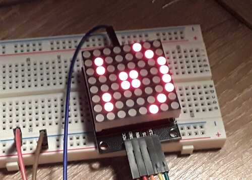
Ahhhh??? Our smiley seems lying!
Orientation of the display
Let's take the partial code of disp-test-3, let's replace
the 0's by points, the 1's by X's:
........
.XX..XX.
........
...XX...
...XX...
X......X
.X....X.
..XXXX..
The smiley is oriented "mouth" down.
One could say that it does not matter. Just reorient the display LED 8x8. If we do this rotation, certainly the smiley will appear as we have programmed it, but physical connectors will prevent us from joining several 8x8 LED displays. The solution is to reorient the smiley in the FORTH code:
: disp-test-4 ( -- ) \ draw face, 18mA needed
    spi.init
    disp.normal
    $01 disp.intensity
    $07 disp.scan.limit
    %00100000 $01 disp.set.digit
    %01000010 $02 disp.set.digit
    %10000010 $03 disp.set.digit
    %10011000 $04 disp.set.digit
    %10011000 $05 disp.set.digit
    %10000010 $06 disp.set.digit
    %01000010 $07 disp.set.digit
    %00100000 $08 disp.set.digit
    begin key? until
    disp.shutdown
    spi.close
;
Which gives the display:
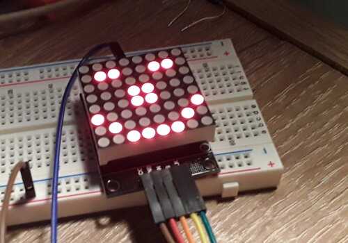
partial code of disp-test-4, 0 -> ., 1 -> X:
..X.....
.X....X.
X.....X.
X..XX...
X..XX...
X.....X.
.X....X.
..X.....
Lean your head to the right. You will recognize the smiley.
So you have to code all the drawings in this way. Yes. But why?
The first line of coding corresponds to the LED display column the most left on the 8x8 LED display:
: disp-test-4 ( -- ) \ draw face, 18mA needed
....
   %00100000 $01 disp.set.digit</b>
...
;
If we delete this line and place it at the end of the sequence, we let's get this:
: disp-test-5 ( -- ) \ draw face, 18mA needed
    spi.init
    disp.normal
    $01 disp.intensity
    $07 disp.scan.limit
    %01000010 $01 disp.set.digit
    %10000010 $02 disp.set.digit
    %10011000 $03 disp.set.digit
    %10011000 $04 disp.set.digit
    %10000010 $05 disp.set.digit
    %01000010 $06 disp.set.digit
    %00100000 $07 disp.set.digit
    %00100000 $08 disp.set.digit
    begin key? until
    disp.shutdown
    spi.close
;
We shifted the smiley display. Any byte coming out of the matrix by the left "reappear" on the right. You now understand the interest of this reorientation of coding of character?
We are close to being able to manage scrolling text!
This is what we will discover in the next article
Scrolling text on an 8x8 LEDS display