LED on and off by interruption
published: 24 May 2020 / updated 15 November 2020

Preamble
For the computer programmer who has very little knowledge of the mechanisms intimate microcontrollers, the concept of interruption is undoubtedly very forbidding.
To illustrate what an interruption is, take the case of a person sitting in front of his TV. This person is watching an exciting match, but is waiting for a package:
- without interruption: every minute, the spectator gets up, goes to the window to see if the postman has arrived;
- with interruption: the spectator put a doorbell on the gate. If the factor arrived, he will hear the bell and get up to get the package.
The spectator without interruption is obliged to share his attention between the match that he tries to watch and monitor the postman's passage to the window.
The spectator with interruption remains quietly in his wheelchair and savor his match. Besides, the postman did not pass and he did not have to get up during all the match...
External Interrupt
Interrupts are signals provided to the CPU of the microcontroller unit, either from internal peripheral modules or from external pins of the MCU. It alters the regular flow of the program execution by enabling the CPU to make a jump to execute instruction routines in some pre-defined location based on the interrupt that occurred. When the CPU completes the routine, it gets back to the location from where it had made a jump.
These pre-defined locations are called as the interrupt vector addresses or interrupt vectors. An interrupt causes the device to save its state of execution and start executing the interrupt handler. For Atmel AVR Microcontrollers the PC register is the only register that will be saved and the stack pointer register is updated in the event of an interrupt. It is up to the user to save other registers like the status register, 32 general purpose registers (register file), on an event of an interrupt, if there is such a requirement in the application.
The interrupts are commonly used to save more time (such as multitasking) than the conventional polling method (waiting for the event to occur indefinitely).
INT0 and INT1 interrupts
On all Arduino boards, there are two particularly interesting interrupts:
INT0 and INT1. On some boards, like the Arduino MEGA board, there are
INT2, INT3, INT4 and INT5 traps.
We will focus on the only INT0 and INT1 interrupts which are
common to all Arduino boards.
Voici les adresses mémoire des interruptions INT0 et INT1:
| Vector no. | Program address |
Source | Port pins | Interrupt definitions |
|---|---|---|---|---|
| 2 | $002 | INT0 |
D2 | External Interrupt Request 0 |
| 3 | $004 | INT1 | D3 | External Interrupt Request 1 |
Steps to configure the Interrupts:
- set INT1 and INT0 bits in the External Interrupt Mask Register (EIMSK)
- configure External Interrupt Control Register A (EICRA) to select interrupt type
- handle the interrupt in the Interrupt Service Routine code.
The INT0 and INT1 interrupts have the particularity of being triggered in four modes:
- Rising Rising indicates that the interrupt function is called each time once the signal goes from LOW to HIGH.
- Falling The second most used mode. Falling indicates that the function interrupt is called each time the signal goes from HIGH to LOW (HIGH to LOW). Falling is necessarily the complement of Rising.
- Change Combines Rising and Falling mode. Consequently, the function interrupt is called each time the signal changes (from High to Low or from Bottom to Top).
- Low In the case of LOW mode, the interrupt function is called cyclically as long as the interrupt signal is low (LOW)
The mode selection is made through the EICRA register:
| ISC11 | ISC10 | ISC01 | ISC00 | ||||
|---|---|---|---|---|---|---|---|
| R/W | R/W | R/W | R/W |
For the interruption INT0, you must act on the bits ISC00 and ISC01:
| ISC01 | ISC00 | Mode |
|---|---|---|
| 0 | 0 | Low |
| 0 | 1 | Change |
| 1 | 0 | Falling |
| 1 | 1 | Rising |
Practical use of the INT0 interrupt
The idea for this article begins with a video posted by 0033mer on Youtube:
In this video, an LED is turned on or off by pressing a button. This button is managed through an interrupt.
The video only shows part of the code used. The following code has been designed from scratch and has nothing to do with the one featured in this video. But he fulfills the same purpose.
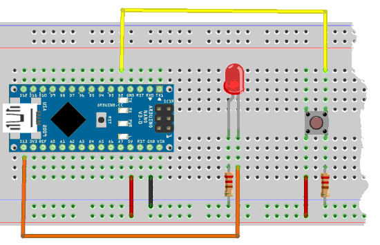
Here is the diagram for mounting an LED and the push button:
LED management
The LED management code is an improved variant. This code is strongly factored. Factoring breaks down each portion of code into units functional identified by words that are simple to understand. This makes the much more readable code.
The words defPIN: high low output input and pin@ are described
in the article Definition and management of PORT connections
\ PORT B
37 constant PORTB	\ Port B Data Register
\ 36 constant DDRB	\ Port B Data Direction Register
\ 35 constant PINB	\ Port B Input Pins

\ PORT D
43 constant PORTD	\ Port D Data Register
\ 42 constant DDRD	\ Port D Data Direction Register
\ 41 constant PIND	\ Port D Input Pins

\ PB5 on Arduino NANO
PORTB %00100000 defPIN: LED
\ PB7 on Arduino MEGA
\ PORTB %10000000 defPIN: LED

: init.ports ( ---)
    LED output    \ set PB5 for output
  ;
The management of the switching on or off of the LED remains trivial:
: LED.on ( ---)
    LED high ;
: LED.off ( ---)
    LED low ;
: LED.toggle ( ---)
    LED pin@
    if      LED low
    else    LED high
    then ;
At this point, it is already possible to test if the LED is well wired and functional:
init.portsinitializes port B to manage the LED;LED.onshould light the LED;LED.offshould turn off the LED;LED.toggleturns off the LED if it is on, turns on the LED if it is off.
Push button management
eeprom
\ PD2 on Arduino NANO
PORTD %00000100 defPIN: BUTTON
\ PD0 on Arduino MEGA
\ PORTD %00000001 defPIN: BUTTON
flash
The following code is not essential for handling the interrupt LED. However, it allows you to check that the push button is working properly:
: button? ( --- fl)
    BUTTON pin@   \ test if button is pressed
    \ true  = button pressed
    \ false = button released
  ;

: button.action ( ---)
    button?
    if
        LED.toggle
    then
  ;
The word button? stacks a true Boolean flag if the push button
is pressed, false if the push button is not pressed In the terminal:
- type
button?, then on the prototyping card, press it push button, keep it pressed. On the keyboard, tap the Enter key. The wordbutton?will execute. If the push button is correctly wired, the execution of the wordbutton?should display -1. - the execution of the word
button?without pressing the push button must display 0.
Interrupt setting
\ EXTERNAL_INTERRUPT
$69 constant EICRA	\ External Interrupt Control Register A
$3d constant EIMSK	\ External Interrupt Mask Register
$0002 constant INT0Addr \ interrupt addr for INT0

: init.interrupt ( ---)
    %00000011 EICRA mset    \ interrupt on rising edge
    %00000001 EIMSK mset    \ activate INT0
  ;
We define the two registers EICRA and EIMSK.
Then we define the address of the INT0 interrupt via the
constant INT0Addr.
The word init.interrupt initializes how the interrupt
INT0 should work:
- The sequence
%00000011 EICRA msetindicates that the interrupt must be trigger on rising edge of the signal; - The sequence
%00000001 EIMSK msetactivates the interrupt INT0
: tempo ( ---)
   3000 for next ; \ adjust the value 3000 if necessary

: int-action ( ---)
    di  \ disable interrupt
    tempo
    LED.toggle
    ei  \ ei = Enable Interrupt
  ;i

: int-enable ( ---)
    ['] int-action INT0Addr int!
    ei  \ ei = Enable Interrupt
  ;

init.ports
init.interrupt
int-enable
The word tempo is used as a timer because you cannot use ms
in an interruption. This time delay must be adjusted if parasitic actions
occur. These parasitic actions are caused by the rebounds of the switch of the
pushbutton.
The word int-action is the one that will be executed by the interrupt INT0.
Its operation is very simple: we deactivate the interrupts (word di),
we delay, switch the state of the LED, then reactivate the interruptions
(word ei).
The word int-enable will validate the interruption by putting the address
execution of the word int-action in the interrupt vector of INT0.
Interrupts are immediately activated.
From this moment, if the push button is pressed, the LED lights up if it was off, or goes out if it was on.
Conclusion
Interrupt management eliminates the need for a loop. In our program, we simply manage toggling the state of an LED.
If you use this button in the traffic light management program, to simulate a passage pedestrian, you can toggle the state of a logical flag. The main loop will test if the flag is active and blocking the lights in favor of a pedestrian crossing.
Mastering interruptions considerably simplifies programming on ARDUINO, in particular to manage transient signals of any kind, but also various internal counters through internal interruptions.