ARDUINO ports: turning on an LED
published: 22 May 2019 / updated 30 April 2020

We could, as in other online documentation, explain how to turn on and off the LED connected to pin 26 (terminal 13), without further explanation.
We will explain - as clearly as possible - the mechanisms that govern the input ports output on the ARDUINO board. At the end of this article, you will master how to manage in FORTH all the ports of your ARDUINO card.
Ports and registers
In this article, we mention the main ports that exist on all ARDUINO boards. Some cards have many more ports.
How ports work
A port is an internal structure of the microcontroller connected to the terminals (pin) of the ARDUINO board.
Port B - on the ARDUINO - manages the pines 19 to 26 (terminals 50 to 53 and 10 to 13
Caution: do not confuse physical connector numbers and pin numbers
On the ARDUINO cards, the physical connectors are marked, some by numbers, others by their function, example: GND, TX, RX, 5V, etc ...
The mapping for associating pin numbers with physical connectors is in this document:
Pin out map on ARDUINO DUE
Pin out map on ARDUINO MEGA 2560
Pin out map on ARDUINO MICRO
Pin out map on ARDUINO NANO
Pin out map on ARDUINO UNO
Pin out map on ARDUINO YUN
For example, the led '13' which is connected to the ARDUINO MEGA board with the physical terminal 13 is related to the PIN 26. In all our texts, the term "pin" will always refer to PIN code XX as referenced in the technical documents of ARDUINO cards. The mention of a physical connector will be done with the term 'terminal'. Example:
PIN 19 (terminal 53) (penultimate terminal, all at the bottom, left on an ARDUINO MEGA 2560 board)
To learn more about how to program the connectors of the different ARDUINO boards:
Understanding ARDUINO card connectors
The way information passes through these terminals is controlled by three registers:
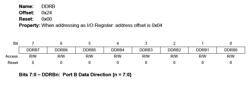
- DDR (Data Direction Register) is the register that determines the direction of circulation of
information:
- 0 = INPUT
- 1 = OUTPUT
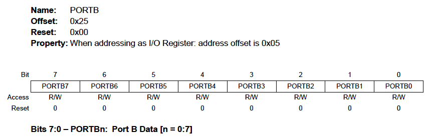
- PORT defines the output status:
- 0 = LOW
- 1 = HIGH
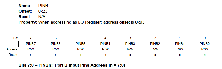
- PIN retrieves the input state:
- 0 = LOW
- 1 = HIGH
To control a port, one injects or takes eight-bit coded values. For the microcontroller ARDUINO, each register is accessible on three different addresses. For example, here is how we would define access to the PORT B registers:
37 constant PORTB
36 constant DDRB
35 constant PINB
The addresses of the registers are given in decimal.
Now, let's go into binary and do some manipulations:
2 base !            \ bascule en base binaire
11111111 DDRB c!    \ positionne tous bits PORTB en sortie
If you refer to the schema structure of the data direction register,
you see that there are eight boxes. By typing 11111111 DDRB c! we have the image
in binary what exactly is asked on this register DDRB for the meaning of
data. For example, if we had wanted to switch to output only half of the bits of
left, we could have typed:
2 base !            \ bascule en base binaire
11110000 DDRB c!    \ positionne tous bits PORTB en sortie
Wouahou! We can binary in FORTH! Oh yes. We can change digital base on the fly. Moreover, let's take advantage of it to know what means 11110000 in decimal:
2 base !
11110000 decimal .  \ affiche 240 - display 240
and in hexadecimal:
2 base !
11110000 hex .      \ affiche f0 - display f0
Specific Flash Forth
With FlashForth, we can indicate if the number is in hexadecimal or binary:
- indicate a number in binary by preceding it with %
- indicate a number in hexadecimal by preceding it with $
Exemple:
%11110000 DDRB c!   \ set PORTB in output
$ff .bin            \ display 11111111
Now, we will turn on the LED connected to pin 13 (pin 26), this famous LED which is
pre-installed on the map. On our ARDUINO Atmega 2560 card, we test all
Bitwise values on PORTB that we have previously defined:
2 base !
00000001 PORTB c!      \ la LED ne s'allume pas - LED off
00000010 PORTB c!      \ la LED ne s'allume pas - LED off
00000100 PORTB c!      \ la LED ne s'allume pas - LED off
00001000 PORTB c!      \ la LED ne s'allume pas - LED off
00010000 PORTB c!      \ la LED ne s'allume pas - LED off
00100000 PORTB c!      \ la LED ne s'allume pas - LED off
01000000 PORTB c!      \ la LED ne s'allume pas - LED off
10000000 PORTB c!      \ la LED s'allume - LED on
We will keep this value 10000000 (128 in decimal, 80 in hexadecimal) to define it as a binary mask:
%10000000 constant PIN26
Manage register in binary
Précédement, nous avons entré cette valeur dans le registre PORTB:
%10000000 PORTB c! \ la LED s'allume - LEB on
Well. Our LED lights up. But the worry is that the other terminals go out.
If there were devices on these other terminals of the PORTB, they
become inoperative.
But before doing some manipulations, we will create a new word .bin
loaded to display an octet on 8 characters in binary:
: .bin  ( c ---)
    base @ >r                       \ récupère base numérique courante
    2 base !                        \ bascule en binaire
    0 <# # # # # # # # # #> type    \ convertit octet en texte binaire
                                    \ et l'affiche sur 8 digits
    r> base ! ;                     \ restaure la base numérique initiale
This new .bin word will display any byte in
binary, regardless of the number base selected. Example:
decimal
255 .bin       \ display 11111111
hex
ff .bin        \ display 11111111
Now let's see how to use the PIN registry:
Let's put some value in the registry PORTB:
52 PORTB c!
Now, let's read what's in PINB:
PINB c@ .bin \ affiche 00110100
The goal is to enable the 10000000 bit in the value 00110100 without changing the other bits:
52 PORTB c!            \ on met valeur 00110100 dans PORTB
PINB c@ .bin           \ affiche 00110100
PIN26 PINB c@ or .bin  \ affiche 10110100
The word or has been applied between the mask defined in the
constant PIN26 and the content retrieved from the registry
PINB. It can be seen that only the most significant bit
was basulated to 1.
We can therefore define our new word led13-on led on physical connector 13:
: led13-on ( ---)
    PINB c@            \ récupère contenu registre PIN du port B
    PIN26 or           \ OU logique avec valeur et masque PIN13
    PORTB c! ;         \ met résultat dans registre PORT du port B
If the LED is off, we test the word led13-on. If you
have followed the explanations and correctly entered the word, the LED
will turn on when running led13-on.
Now let's see how to turn off the LED. To do this, we recover the mask of
bit on which we make a xor with the decimal value 255
(11111111 in binary). Then we get the value of the PINB register
and we make a logical and. We put the result back into
register PORTB:
: led13-off ( ---)
    PINB c@             \ on récupère le contenu du registre PIB du port B
    PIN26 255 xor       \ on récupère le masque de bit et on inverse les bits
    and PORTB c! ;      \ ET logique et remet valeur dans registre PORT B
Running led13-off turns off the LED.
With a few constants and two definitions, so we can turn on and selectively turn off an LED, the famous LED of the PIN26 (physical terminal 13).
But most importantly, we can interact in real time and view content register PINB, which is a real asset in the development of functions.
In summary, our LED control program 13:
\ non optimised FORTH code
decimal
-blink
marker -blink
37 constant PORTB
36 constant DDRB
35 constant PINB
2 base !
10000000 constant pin26
decimal
: init-ddrb ( ---)
    pin26 DDRB c@ or
    DDRB c! ;
: led13-on ( ---)
    PINB c@            \ get content PIN register for port B
    pin26 or           \ logic OR with mask value pin13
    PORTB c! ;         \ push result in register PORT for port B
: led13-off ( ---)
    PINB c@             \ get content of register PIN for port B
    pin26 255 xor       \ get bit mask pin26 and toggle bit
    and PORTB c! ;      \ logic AND eand push value in register PORT fort port B
: blinking ( ---)       \ boucle de clignotement
    init-ddrb
    begin
        led13-on   500 ms
        led13-off  500 ms
    key? until ;
\ Utilisation:
\  led13-on    \ set LED ON for PIN 13
\  led13-off   \ set LED OFF for PIN 13
\  blinking    \ infinite loop for blinking
The complete listing and documented is available here.
Once compiled, this program occupies less than 300 bytes of memory flash.
Code optimisé pour FlashForth
\ optimised FORTH code
-blink
marker -blink
37 constant PORTB
36 constant DDRB
35 constant PINB
%10000000 constant pin26
: init-ddrb ( ---)
    pin26 DDRB mset ;
: led13-on ( ---)
    pin26 PORTB mset ;
: led13-off ( ---)
    pin26 PORTB mclr ;
: blinking ( ---)       \ boucle de clignotement
    init-ddrb
    begin
        led13-on   500 ms
        led13-off  500 ms
    key? until ;
Automatic start of the program
In order for the flashing to be operational when the card is booted, it indicate the word we wish to execute when starting the ARDUINO board.
If the word blinking works well after compiling, type this:
' blinking is turnkey
Then disconnect the power supply from your Arduino board. Wait two or three seconds, then reconnect power electrical board Arduino. In one second, the ARDUINO card works and the LED should blink!
Through this very first example, we explained detailed all the ins and outs on the management of ports in simple entry / exit, realized a real program that gets under way when starting the Arduino board.
To interrupt the flashing loop, connect the card to USB and start
the terminal. In principle, pressing a key on the keyboard transmits a character
which interrupts blinking. Then type:
false is turnkey
Port A
decimal
\ PORTA
34 constant PORTA	\ Port A Data Register
33 constant DDRA	\ Port A Data Direction Register
32 constant PINA	\ Port A Input Pins
Port A is used for analog inputs/outputs. It can also be operated for digital inputs/outputs.
Ports B, C and D
The processor on all Arduino boards has at least 3 ports: B, C, and D.
Some ARDUINO cards have many more ports, the MEGA 2560 card case. The ATmega8 and ATmega168 cards have only three ports.
Each port is controlled by three registers.
decimal
\ PORTB
37 constant PORTB	\ Port B Data Register
36 constant DDRB	\ Port B Data Direction Register
35 constant PINB	\ Port B Input Pins
\ PORTC
40 constant PORTC	\ Port C Data Register
39 constant DDRC	\ Port C Data Direction Register
38 constant PINC	\ Port C Input Pins
\ PORTD
43 constant PORTD	\ Port D Data Register
42 constant DDRD	\ Port D Data Direction Register
41 constant PIND	\ Port D Input Pins
This part of code is valid for all Arduino boards.
Other ports
For other cards, here are the additional ports needed:
decimal
\ PORTE
46 constant PORTE	\ Data Register, Port E
45 constant DDRE	\ Data Direction Register, Port E
44 constant PINE	\ Input Pins, Port E
\ PORTF
49 constant PORTF	\ Data Register, Port F
48 constant DDRF	\ Data Direction Register, Port F
47 constant PINF	\ Input Pins, Port F
\ PORTG
52 constant PORTG	\ Data Register, Port G
51 constant DDRG	\ Data Direction Register, Port G
50 constant PING	\ Input Pins, Port G
\ PORTH
258 constant PORTH	\ PORT H Data Register
257 constant DDRH	\ PORT H Data Direction Register
256 constant PINH	\ PORT H Input Pins
\ PORTJ
261 constant PORTJ	\ PORT J Data Register
260 constant DDRJ	\ PORT J Data Direction Register
259 constant PINJ	\ PORT J Input Pins
\ PORTK
264 constant PORTK	\ PORT K Data Register
263 constant DDRK	\ PORT K Data Direction Register
262 constant PINK	\ PORT K Input Pins
\ PORTL
267 constant PORTL	\ PORT L Data Register
266 constant DDRL	\ PORT L Data Direction Register
265 constant PINL	\ PORT L Input Pins
In the following chapter, we will see how to homogenize all this: ARDUINO ports: manage a trafic light