Execute a hardware interrupt
published: 5 June 2019 / updated 26 June 2019

Preamble
We have already discussed an interesting example with a traffic light: ARDUINO ports: manage a trafic light.
To be complete, the traffic lights can also be a pedestrian crossing. Such a passage two ways of working:
- automatic : the pedestrian light there are pedestrians waiting or nobody;
- manual: the fire of pedestrian with a button to activate to trigger a passage pedestrian in green interrupting the rest of the car traffic;
But we managed our traffic light program through a permanent loop with timers. The worry, with these timers, is one pedestrian asked the fire green during one of these delays, its request will be ignored, except to remain supported long enough for the fire management cycle detected this button support.
The elegant solution, without going through several tasks, is to manage this button through an interruption.
The principle of an interruption is a process independent of the main program. In our example,
our flag, like true ATTENTE-PIETON !.
Then load the traffic lights management loop to take into account this request and treat it.
In the rest of this article, we will not go back to the management of traffic lights, but simply show how - in FORTH language - we manage a push button by interruption.
ARDUINO board interrupts
On the ARDUINO boards, a certain number of pins can be used in interrupts. Enabling or disabling these pins can trigger independent actions a main loop.
With Flash FORTH, you can execute a word in particular. For our case, here it will be the support of a button that will trigger an action.
Here is the diagram of our assembly:
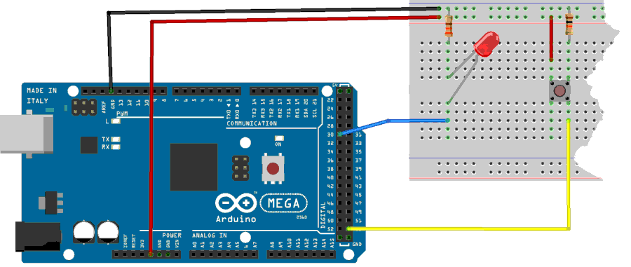
Button management on pin 19
Caution: do not confuse physical connector numbers and pin numbers
On the ARDUINO cards, the physical connectors are marked, some by numbers, others by their function, example: GND, TX, RX, 5V, etc ...
The mapping for associating pin numbers with physical connectors is in this document:
Pin out map on ARDUINO DUE
Pin out map on ARDUINO MEGA 2560
Pin out map on ARDUINO MICRO
Pin out map on ARDUINO NANO
Pin out map on ARDUINO UNO
Pin out map on ARDUINO YUN
For example, the led '13' which is connected to the ARDUINO MEGA board with the physical terminal 13 is related to the PIN 26. In all our texts, the term "pin" will always refer to PIN code XX as referenced in the technical documents of ARDUINO cards. The mention of a physical connector will be done with the term 'terminal'. Example:
PIN 19 (terminal 53) (penultimate terminal, all at the bottom, left on an ARDUINO MEGA 2560 board)
To learn more about how to program the connectors of the different ARDUINO boards:
Understanding ARDUINO card connectors
The button connected to pin 19 (terminal 53) is managed by PORT B:
37 constant PORTB    \ définition registre PORT du port B
36 constant DDRB     \ définition registre DDR  du port B
35 constant PINB     \ définition registre PIN  du port B
The position of this bread in the PORTB register is the least significant bit:
%00000001 constant pin19 \ masque pin 19
The word pin19? retrieves the state of this button:
: pin19? ( --- fl)
    PINB c@          \ empile contenu registre PIN du port B
    pin19 and        \ ET logique avec masque PIN12
    0=               \ si nul
    if      false    \ empile FALSE
    else    true     \ empile TRUE
    then ;
Finally, we initialize PORT B:
: init-ddrb ( ---)   \ initialise PORTB en entrée sur tous les bits
    $00 DDRB c!      \ active pins en entrée sur PORT B
  ;
Here's how to test if the button is connected:
init-ddrb  ok<#,ram>
pin19?  ok<#,ram> 0
pin19?  ok<#,ram> 0 65535
This is the copy of the test run: init-ddrb initializes
the PORTB. pin19? without pressing the button stacks 0 (false).
pin19? with pushbutton button stacks 65535 (true).
Management of the LED on the pin 60 (PC7)
We define the registers of PORT C:
\ PORTC
40 constant PORTC	\ Port C Data Register
39 constant DDRC	\ Port C Data Direction Register
38 constant PINC	\ Port C Input Pins
Then, the position of the pin 60 in the PORTB is determined:
%10000000 constant pin60 \ masque binaire du PIN60 (PC7)
We create the word init-ddrc which will indicate the pin 60 in output:
: init-ddrc ( ---)
    pin60 DDRC mset       \ active pins en sortie sur PORT C
  ;
And finally the words to turn on, turn off and know the state of the LED connected to pin 60:
: pin60on ( ---)
    pin60 PORTC mset
    ;
: pin60off ( ---)
    pin60 PORTC mclr
    ;
: pin60? ( --- fl)      \ récupère état LED connectée au pin 30
    pin60 PORTC mtst
    ;
We test these three new words:
init-ddrc  ok<#,ram>
pin60on  ok<#,ram>
pin60?  ok<#,ram> 65535
pin60off  ok<#,ram>
pin60?  ok<#,ram> 65535 0
If everything went well, the LED on pin 60 turned on and off.
Choice of interruption
According to the ARDUINO card, we have a number of hardware interrupts. For the MEGA2560 R3 card,
list of interrupts sayPCINT (P in C change INTerrupt)
PCINT0 on pin 19 (physical connector 53)
PCINT1 on pin 20 (physical connector 52)
PCINT2 on pin 21 (physical connector 51)
PCINT3 on pin 22 (physical connector 50)
PCINT4 on pin 23 (physical connector 10)
PCINT5 on pin 24 (physical connector 11)
PCINT6 on pin 25 (physical connector 12)
PCINT7 on pin 26 (physical connector 13)
We initialize the interrupt vector:
\ ATTENTION: spécifique Mega 2560
10  constant PCINT0     \ numéro vecteur interruption 4 pour PCINT0
$6b constant PCMSK0     \ Pin Change Mask Register 0
104 constant PCICR	\ Pin Change Interrupt Control Register $68
We will now exploit this material interruption. But for her
is effective, we will generate a waiting loop. This loop does not
call to the word ms which generates conflicts with our interruption:
: attente ( n ---)
    for next ;
The word attente creates a small delay, thus limiting the
rebound phenomenon generated by physical push buttons. We go
now manage the toggle of the LED that will be lit when the button is
activated, otherwise off when the button is released:
: toggleLED ( ---)
    di                  \ désactivation interruptions
    10000 attente
    pin19?              \ récupère état bouton poussoir
    if                  \ si enfoncé, on bascule état LED
        pin60?
        if      pin60off \ si allumée, éteint LED
        else    pin60on  \ si éteinte, allume LED
        then
    then
    ei                  \ réactivation interruption
;i

: int-enable
    ['] toggleLED PCINT0 int!
    ei                  \ ei = Enable Interrupt
;
int-enable
%00000001 PCMSK0 mset
%00000111 PCICR  mset

init-ddrb
init-ddrc
We do not need to run toggleLED. Just pressing the
push button turns the LED on or off.
Note that the definition of toggleLED ends with the word ;i.
Any word definition handled by an interrupt must end with ;i
on pain of crashing FORTH.
The interrupt vectors are stored in ram. The interrupt vectors in ram are cleared at warm start,
so to enable the interrupt int-enable at startup, a initialization word must be used:
' int-enable is turnkey
Thus, by powering down and restarting the ARDUINO board, the interrupt will be reactivated and operational.