ARDUINO ports: manage a trafic light
published: 25 May 2019 / updated 4 June 2020

Digital ports
Let's go back in more detail on the functioning of the digital ports. To do this, we we will only process the PORT B. This port is accessible in FORTH through three registers:
- DDR (Data Direction Register) is the register that determines the direction of circulation of news
- PORT sets the exit status
- PIN retrieve the input state
Caution: do not confuse physical connector numbers and pin numbers
On the ARDUINO cards, the physical connectors are marked, some by numbers, others by their function, example: GND, TX, RX, 5V, etc ...
The mapping for associating pin numbers with physical connectors is in this document:
Pin out map on ARDUINO DUE
Pin out map on ARDUINO MEGA 2560
Pin out map on ARDUINO MICRO
Pin out map on ARDUINO NANO
Pin out map on ARDUINO UNO
Pin out map on ARDUINO YUN
For example, the led '13' which is connected to the ARDUINO MEGA board with the physical terminal 13 is related to the PIN 26. In all our texts, the term "pin" will always refer to PIN code XX as referenced in the technical documents of ARDUINO cards. The mention of a physical connector will be done with the term 'terminal'. Example:
PIN 19 (terminal 53) (penultimate terminal, all at the bottom, left on an ARDUINO MEGA 2560 board)
To learn more about how to program the connectors of the different ARDUINO boards:
Understanding ARDUINO card connectors
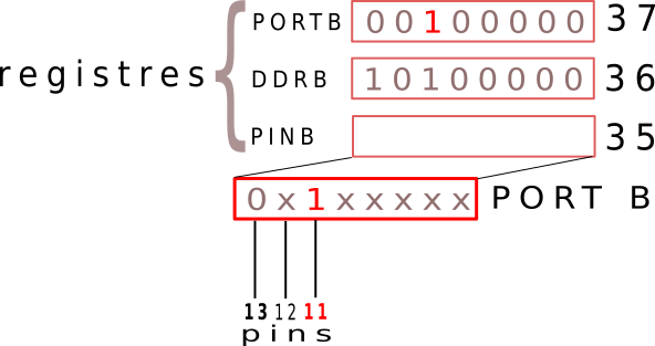
Here is a diagram showing the link between these registers and the associated port:
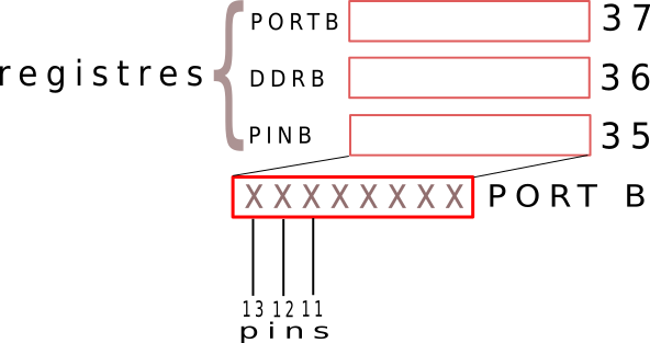
In PORT B, the "X" indicate an indeterminate state of this port.
Before activating or deactivating a PIN, you must indicate in the DDR register of PORT B, here DDRB which pins are in or out.
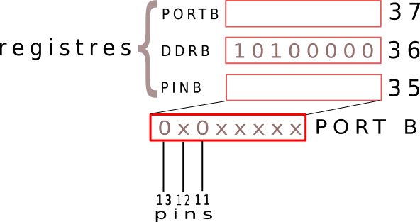
Only PINs 24 and 26 should be output (terminals 11 and 13). So you have to drop
in this DDR register the binary value 10100000 (160 in decimal, A0 in hexadecimal).
To do this, it is necessary to write to the decimal address 36 the value 160. We thus define beforehand three constants:
\ PORTB
37 constant PORTB	\ Port B Data Register
\ 36 constant DDRB	\ Port B Data Direction Register
\ 35 constant PINB	\ Port B Input Pins
The DDR register
To act on the DDRB registry, we could have written this:
160 36 c! \ met 160 dans DDRB, 10100000 en binaire
But it is more explicit to write this:
160 DDRB c! \ met 160 dans DDRB, 10100000 en binaire
The word C! (c addr ---) stores an 8-bit value at the address addr. On the Arduino board,
these low addresses are exploited by the port registers. Here is what it gives on our diagram:
The PORT register
It is this register which makes it possible to say which pin must be activated or not:
- an activated pine delivers a positive voltage of low intensity, but sufficient to turn on an LED.
- a disabled pin does not deliver voltage.
Activate PIN 26. To do this, you must inject the binary value 10000000
in the PORTB register. Diagram:
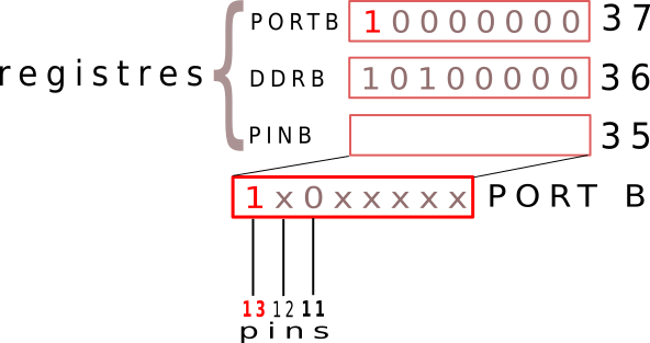
Code correspondant:
128 37 c! \ met 128 dans registre PORT B, 10000000 en binaire
Who can also write:
128 PORTB c! \ met 128 dans registre PORT B, 10000000 en binaire
To activate pin 11:
Ah damn! We turned off the pine 26 and only lit the pine 24.
So we have to find a way to selectively turn on or off pines without alter the state of those who are active or not active. For example, how to light pin 26 without turning off pin 11 if it is already active?
Let's see this in a little binary juggling ...
Binary juggling
Take the values injected into the PORTB register, this without taking into account DDR register status report:
128 PORTB c!            \ pin 26: 10000000  128  80
 64 PORTB c!            \ pin 26: 01000000   64  40
 32 PORTB c!            \ pin 26: 00100000   32  20
 16 PORTB c!            \ pin 26: 00010000   16  10
Let's take a close look at the injected binary values to activate selectively a pine:
10000000 80

    01000000 40

    00100000 20

    00010000 10
The bits 1 correspond to the position of the pin in the DDR and PORT registry.
We will use this value as mask to set the PINs.
To do this, we will create the word defPIN: like this:
The words defPIN: high low output input and pin@ are described
in the article Definition and management of PORT connections
In FORTH, there are words of creation of words: : constant variable , etc ...
The word defPIN: is now a new word creation word, word having
as the sole purpose of creating "PINs":
\ définition pinXX
PORTB $80 defPIN: LED.red
PORTB $40 defPIN: LED.yellow
PORTB $20 defPIN: LED.green
What does the word LED.red next, for example:
\ définition pinXX
LED.red   \ empile   128 37
So we find on the stack two values: 128 which is the "mask" that
we will handle further and then 37 which is the address of the
register PORTB
Turn on a bit in a register
Let's go crazy and activate all the bits of PORT B:
$ff DDRB  c!
$ff PORTB c!
There, if you have LEDs connected to pins 24 to 26, they should light up. Otherwise, trust us!
Now, let's turn them off:
$00 PORTB c!
So we have 00000000 in the PORTB register. It is therefore
to turn on pin12 which has the mask 01000000. We are going to use
this "mask" like this:
%00000000      \ valeur PORTB
%01000000 or   \ fait OU logique, reste 010000000 sur la pile
At any time, we can recover the contents of the PORTB registry like this:
PORTB c@ \ empile contenu du registre PORTB
If we have not changed the contents of PORTB in the meantime, we must find 01000000. activate
now the pin24 that has the "mask" in binary 00100000:
2 base !
01000000      \ valeur PORTB
00100000 or   \ fait OU logique, reste 011000000 sur la pile
Here is the whole sequence to activate the LED.red as it is typed on the Arduino programmable in FORTH (text capture - comments have been added):
LED.red  ok<#,ram> 128 37     \ récupère masque LED.red et adresse PORTB
dup  ok<#,ram> 128 37 37    \ duplique adresse PORTB
c@  ok<#,ram> 128 37 0      \ récupère contenu PORTB
rot  ok<#,ram> 37 0 128     \ met masque LED.red au sommet de la pile
or  ok<#,ram> 37 128        \ OU logique => laisse val sur pile
swap  ok<#,ram> 128 37      \ inverse pour avoir  val adrPORTB
c!  ok<#,ram>               \ envoie val dans PORTB
Now that LED.red is active, let's see how to activate LED.green:
LED.green  ok<#,ram> 32 37
dup  ok<#,ram> 32 37 37
c@  ok<#,ram> 32 37 128
rot  ok<#,ram> 37 128 32
or  ok<#,ram> 37 160
swap  ok<#,ram> 160 37
c!  ok<#,ram>
Now let's see how to selectively shut down a pin.
Turn off a bit in a register
It's hardly a bit more acrobatic. Comments have been added:
LED.green   ok<#,ram> 32 37  \ récupère masque LED.green et adresse PORTB
dup  ok<#,ram> 32 37 37     \ duplique adresse PORTB
c@  ok<#,ram> 32 37 160     \ récupère contenu PORTB
rot  ok<#,ram> 37 160 32    \ met masque LED.green au sommet de la pile
$ff  ok<#,ram> 37 160 32 255 \ met 11111111 (FF) au sommet pile
xor  ok<#,ram> 37 160 223   \ XOR logique (inrse bits) => laisse val sur pile
and  ok<#,ram> 37 128       \ ET logique avec contenu PORTB
swap  ok<#,ram> 128 37      \ inverse pour avoir  val adrPORTB
c!  ok<#,ram>               \ envoie val dans PORTB
Heureusement, nous avons les mots high et low qui simplifient
ces manipulations:
LED.green high \ turn on green LED
Manage a traffic light
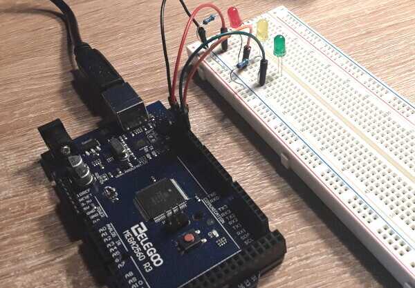
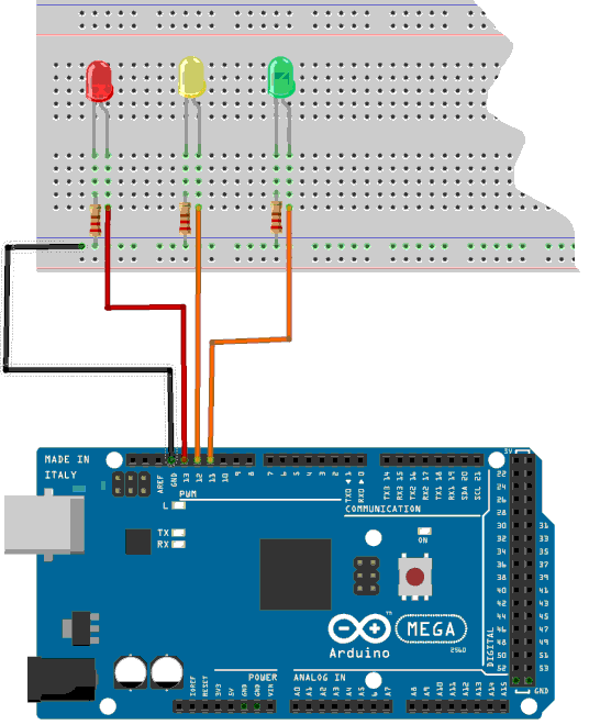
As an example, implement this by connecting 3 LEDs:
- green on pin 24
- yellow on pin 25
- red on pin 26
Let's create 6 words to selectively enable and disable each pin:
For each LED, let's plan an activation time:
: feu-vert ( n ---)
    LED.green high
    ms              \ n valeur délai d'allumage en millisecondes
    LED.green low ;
: feu-orange ( n ---)
    LED.yellow high
    ms              \ n valeur délai d'allumage en millisecondes
    LED.yellow low ;
: feu-rouge ( n ---)
    LED.red high
    ms              \ n valeur délai d'allumage en millisecondes
    LED.red low ;
If you enter 1000 feu-vert, the green LED lights for one second. Let's put this
in application in a new word feux-tricolores:
: feux-tricolores ( ---)
    \ valeurs 3000 500 et 3000 corespondent au délai en millisecondes
    \ d'activation de chaque feu.
    3000 feu-vert
    500  feu-orange
    3000 feu-rouge ;
\ feux-tricolores exécute un seul cycle de feux
Running the traffic light will trigger a single fire cycle.
For this cycle to be repeated, we put everything in an infinite loop:
: feux ( ---)
    init-feux
    begin
        feux-tricolores
    key? until ;
The execution of lights can be interrupted simply by
tapping a key on the keyboard.
Manage a German traffic light
You love managing fire so much that you have a customer in Germany. But there, the fires work a little differently from those in France. Certainly the green goes orange then red. But before coming back to green, both red and orange lights light up simultaneously.
Do not get sweaty to call a computer cracker. It's flaring in two stages:
\ variante feux allemands
: feu-mixte ( n ---)
    LED.yellow high        \ allume feu rouge et orange en même temps
    LED.red high
    ms              \ n valeur délai d'allumage en millisecondes
    LED.yellow off
    LED.red low ;
: feux-allemands ( ---)
    init-feux
    begin
        3000 feu-vert
        500  feu-orange
        3000 feu-rouge
        500 feu-mixte
    key? until ;
The complete and functional listing is available here.
Conclusion
The last words defined in this article, namely feux and
feux-allemands show that thanks to certain words in French
the code is quite readable.
At the risk of insisting, the strong point of the FORTH language is to allow the testing of words very simple in situ, ie directly on the Arduino board. This is impossible in C language.