ARDUINO ports: K2000 maze
published: 29 May 2019 / updated 30 June 2019

article: 29 mai 2019 / mis à jour 30 juin 2019
Manage multiple pins simultaneously
Let's go back to our management of traffic lights. In this code, we manage each pin separately:
: pin13-on ( ---)
    pin13 HIGH digitalWrite ;
: pin13-off ( ---)
    pin13 LOW digitalWrite ;
: pin12-on ( ---)
    pin12 HIGH digitalWrite ;
: pin12-off ( ---)
    pin12 LOW digitalWrite ;
: pin11-on ( ---)
    pin11 HIGH digitalWrite ;
: pin11-off ( ---)
    pin11 LOW digitalWrite ;
With this code, the disadvantage is that you must then sequentially manage each fire:
: feux-tricolores ( ---)
    \ valeurs 3000 500 et 3000 corespondent au délai en millisecondes
    \ d'activation de chaque feu.
    3000 feu-vert
    500  feu-orange
    3000 feu-rouge ;
\ feux-tricolores exécute un seul cycle de feux
We wrote the code of the word digitalWrite so as not to alter
the condition of the other pines. This is interesting for more general applications, but in
the special case of managing our traffic light, the simultaneous crash of several
bits in the PORTB register may be unproductive.
Caution: do not confuse physical connector numbers and pin numbers
On the ARDUINO cards, the physical connectors are marked, some by numbers, others by their function, example: GND, TX, RX, 5V, etc ...
The mapping for associating pin numbers with physical connectors is in this document:
Pin out map on ARDUINO DUE
Pin out map on ARDUINO MEGA 2560
Pin out map on ARDUINO MICRO
Pin out map on ARDUINO NANO
Pin out map on ARDUINO UNO
Pin out map on ARDUINO YUN
For example, the led '13' which is connected to the ARDUINO MEGA board with the physical terminal 13 is related to the PIN 26. In all our texts, the term "pin" will always refer to PIN code XX as referenced in the technical documents of ARDUINO cards. The mention of a physical connector will be done with the term 'terminal'. Example:
PIN 19 (terminal 53) (penultimate terminal, all at the bottom, left on an ARDUINO MEGA 2560 board)
To learn more about how to program the connectors of the different ARDUINO boards:
Understanding ARDUINO card connectors
Overwrite multiple values
We will see how, in FORTH language, to overwrite several bits in a port register on our Arduino board. But before that, a little reminder about binary coding for those who are not used to this coding.
Recall on binary coding
FORTH is both a low-level language because some words are pretty close to the machine code. But FORTH is also a language of high level because the definition of easy-to-understand words is fast.
In the rest of this article, we will do many manipulations of low level and using a maximum of binary coding.
Binary coding makes it possible to understand the values that we inject into the registers AtMega micro-controller ports.
Numeric values on eight bits (one byte) are ALWAYS located in an interval 0..255 in decimal. The value 256 exceeds 8 bits. If you count the number of valeus located between 0 and 255, you have 256 values.
We have three words in FORTH on the Arduino board to change the number base:
decimalselects the decimal numerical base (selected by default when FORTH starts),hexselects the hexadecimal numeric base,binselects the binary digital base.
The lowest value that a byte can take is 0 (zero), regardless of the number base.
The highest value that a byte can take is 255, regardless of the numeric base:
decimal 255 bin .   \ display 11111111
decimal  32 bin .   \ display 100000
Here, the value 32 gives in binary 100000. To have 8 bits, one supplements mentally
the left part with the missing 0s:00100000
The same test in hexadecimal:
decimal 255 hex .   \ display ff
decimal  32 hex .   \ display 20
Here! So you can easily convert binary to decimal or hexadecimal:
bin 11100000 decimal .   \ display 224
bin 11100000 hex     .   \ display e0
Let's go back to our traffic light. So we're going to turn on the green LED, but by turning off the other two LEDs. The red LED is connected to pin 13, the yellow LED at pin 12 and the green LED at pin 11:
bin
00100000 PORTB c!  \ allume LED verte   éteint les autres
01000000 PORTB c!  \ allume LED jaune   éteint les autres
10000000 PORTB c!  \ allume LED rouge   éteint les autres
Let's define a word cycleFr to manage a fire cycle as managed in France:
: attente-normale 1000 ms ;          \ tempo une seconde
: attente-courte   300 ms ;          \ tempo 3/10ème seconde
bin
: cycle-fr ( ---)
    00100000 PORTB c!  \ allume LED verte   éteint les autres
    attente-normale
    01000000 PORTB c!  \ allume LED jaune   éteint les autres
    attente-courte
    10000000 PORTB c!  \ allume LED rouge   éteint les autres
    attente-normale
    ;
decimal
We can immediately test the word cycle-fr:
bin
11100000 DDRB c!   \ met pin 11 à 13 en SORTIE
decimal
cycle-fr           \ exécute un cycle de feux
The red light stays on. it's normal. But if we put cycle-en
in a loop, the lighting of the green LED turns off the red LED:
: feux ( ---)
    $e0 DDRB c!  \ E0 in hexa is same as 11100000 in binary
    begin
        cycle-fr
    key? until
    $00 PORTB !
    ;
Defining a German trafic lighr is hardly more complicated:
: cycle-de ( ---)
    00100000 PORTB c!  \ allume LED verte   éteint les autres
    attente-normale
    01000000 PORTB c!  \ allume LED jaune   éteint les autres
    attente-courte
    10000000 PORTB c!  \ allume LED rouge   éteint les autres
    attente-normale
    11000000 PORTB c!  \ allume LED jaune et rouge   éteint les autres
    attente-courte
    ;
The complete listing is available here.
A K2000 effect
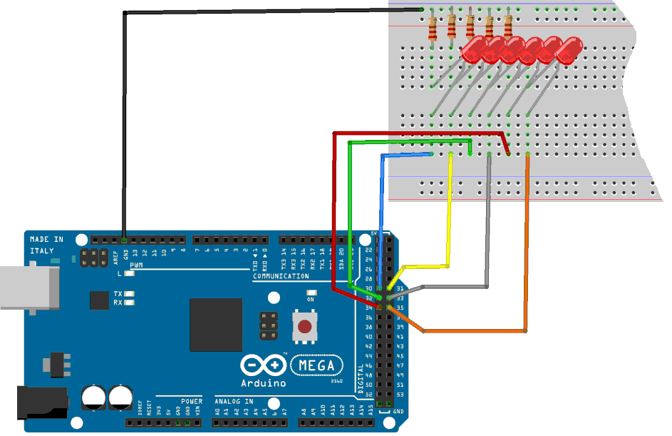
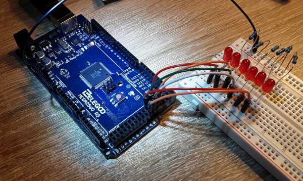
To make a chase effect, we chose to manage the PORT C on which are mounted pins 30 to 37. For our chase, we have mounted only 6 LEDs:
Sample code to handle a very simple chase:
: init-ddrc ( ---)      \ initialise PORTC en sortie sur tous les bits
    $ff DDRC c!         \ active pins en sortie sur PORT C
  ;
: scroll-avt ( ---)     \ effet scroll vers avant
    $80 PORTC c!  100 ms    \ 10000000
    $40 PORTC c!  100 ms    \ 01000000
    $20 PORTC c!  100 ms    \ 00100000
    $10 PORTC c!  100 ms    \ 00010000
    $08 PORTC c!  100 ms    \ 00001000
    $04 PORTC c!  100 ms    \ 00000100
  ;
The values to be injected in the address pointed by PORTC are in hexadecimal.
The equivalent values in binary are in comments. It clearly shows the
"1" that shifts from left to right. It is this "1" that will light sequentially
the LEDs if we execute scroll-avt. At the end of the chase, the last LED
is still on. It is extinguished by hand for the moment:
0 PORTC c!
Now that our LED has crawled from left to right, here's how the make come back:
: scroll-ret ( ---)     \ effet scroll vers arrière
    $04 PORTC c!  100 ms
    $08 PORTC c!  100 ms
    $10 PORTC c!  100 ms
    $20 PORTC c!  100 ms
    $40 PORTC c!  100 ms
    $80 PORTC c!  100 ms
  ;
We check the functioning of this word by typing scroll-ret.
And we pack all this in an indefinite loop:
: boucle-scroll ( ---)
    init-ddrc
    begin
        scroll-avt
        scroll-ret
    key? until
    $00 PORTC c!
  ;
And our effect on the K2000 in its loop:
: k2000 ( ---)
    init-ddrc
    begin
        kitt-scroll
    key? until
    $00 PORTC c!
  ;
You test by typing k2000 and if everything is OK, your
if LEDs make you a great chase effect to the K2000 ....
The complete listing is available here.
So far, we've only managed output information by turning on and off
turning off LEDs. Now let's go to input information processing
in the following chapter:
ARDUINO ports: manage a push button