ARDUINO ports: manage a push button
published: 29 April 2024 / updated 29 April 2024

article: 29 mai 2019 / mis à jour 30 juin 2019
We will use a push button:
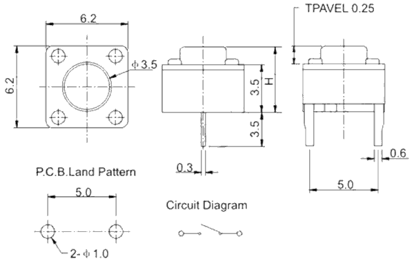
The one we use has 4 terminals, but its operation does not differ from that shown in the diagram above.
Caution: do not confuse physical connector numbers and pin numbers
On the ARDUINO cards, the physical connectors are marked, some by numbers, others by their function, example: GND, TX, RX, 5V, etc ...
The mapping for associating pin numbers with physical connectors is in this document:
Pin out map on ARDUINO DUE
Pin out map on ARDUINO MEGA 2560
Pin out map on ARDUINO MICRO
Pin out map on ARDUINO NANO
Pin out map on ARDUINO UNO
Pin out map on ARDUINO YUN
For example, the led '13' which is connected to the ARDUINO MEGA board with the physical terminal 13 is related to the PIN 26. In all our texts, the term "pin" will always refer to PIN code XX as referenced in the technical documents of ARDUINO cards. The mention of a physical connector will be done with the term 'terminal'. Example:
PIN 19 (terminal 53) (penultimate terminal, all at the bottom, left on an ARDUINO MEGA 2560 board)
To learn more about how to program the connectors of the different ARDUINO boards:
Understanding ARDUINO card connectors
Manage a push button
This button is connected to pin 12 (the one just before LED 13 / pin 13). here is the code to read its state:
37 constant PORTB    \ définition registre PORT du port B
36 constant DDRB     \ définition registre DDR  du port B
35 constant PINB     \ définition registre PIN  du port B
: .pin12 ( ---)
    PINB c@ .        \ lecture registre PIN du port B
  ;
Our word .pin12 is very simple. It reads the contents of the Port B PIN register.
When using .pin12 for the first time, you must initialize the DDR register:
0 DDRB c!            \ initialise tout le registre DDR du port B en entrée données
.pin12               \ empile 128 --> valeur à vide pin 13
Now, let's press the push button and then rerun .pin12:
.pin12 \ empile 192
Let's look at what these values give in binary:
(128) 10000000
(192) 11000000
We have set the bit that has been modified red. This is the 7th bit whose mask, in
binary is 01000000...
Well? This is the same mask we used to define pin12
in this article:
\ définition pinXX
    ...

    PORTB $40 defPIN: pin12
The hex value 40 equal 01000000 in binary.
Manage the button in simple push
So, to know if it is the AND button only the push button connected to the pin
12 that is activated, we will define the word pin12?:
: pin12? ( --- fl)
    PINB c@          \ empile contenu registre PIN du port B
    $40 and          \ ET logique avec masque 01000000 pin 12
    0=               \ si nul
    if
        false        \ empile FALSE
    else
        true         \ empile TRUE
    then
  ;
The word pin12? performs a push test of the connected push button
to pin 12. If the button is not pressed, stack 0, otherwise stack 65535.
the value 65535 ands the numeric value for true. We will
use this to turn on a led on port C.
To tap the button connected to pin 12, let's rewrite the LED management connected to pine 30:
\ PORTC
40 constant PORTC	\ Port C Data Register
39 constant DDRC	\ Port C Data Direction Register
38 constant PINC	\ Port C Input Pins

: init-ddrc ( ---)      \ initialise PORTC en SORTIE sur tous les bits
    $ff DDRC c!         \ active pins en sortie sur PORT C
  ;
: pin30on ( ---)
    PORTC c@
    $80 or              \ OU logique avec valeur récupérée sur PORTC
    PORTC c! ;
: pin30off ( ---)
    PORTC c@
    $80 $ff xor and     \ OU eXclusif puis AND pour mettre à 0 8ème bit
    PORTC c! ;
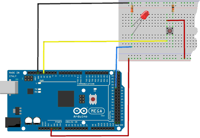
Wiring diagram of our push button:
Running pin30on turns on the LED, pin30off
turn off the LED:
init-ddrc       \ initialise PORTC en SORTIE sur tous les bits
pin30on         \ allume LED sur pin 30
pin30off        \ éteint LED sur pin 30
And now, a little indefinite loop to turn on and off the LED:
: allumeLED ( ---)
    begin
        pin12?          \ bouton activé
        if
            pin30on     \ si oui, allume LED
        else
            pin30off    \ si non, éteint LED
        then
    key?
    until ;
One runs allumeLED: pressing the push button turns on
the LED, releasing the same button turns off the LED.
The complete listing is available here.