Understanding binary coding with FORTH
published: 29 April 2024 / updated 29 April 2024

article: 15 juin 2019 / mis à jour 01 mai 2020
When exploiting logical functions, such as
AND OR XOR or the test result = > < <>, it becomes
essential to understand the binary coding which is far from being a simple
arithmetic representation a bit exotic.
In the rest of this article, examples will often be presented in FORTH language. All of these examples have been tested with gForth versions (on PC) and FlashForth (on ARDUINO).
If you do not know the FORTH language, explanations about binary coding and their application to other languages will remain valid.
The binary code
The modern binary number system, based on the binary code, was invented
by Gottfried LEIBNITZ in 1689 and appears in his article Explanation of
Binary Arithmetic
in 1703.
In 1847, Georges BOOLE published an article entitled Mathematical Analysis of Logic
which explains an algebraic system of binary logic. His works were forgotten
until 1937, when Claude SHANNON discovered that BOOLE algebra could apply
to electrical circuits.
Electrical circuits
Here is the simplest electrical circuit you can imagine:
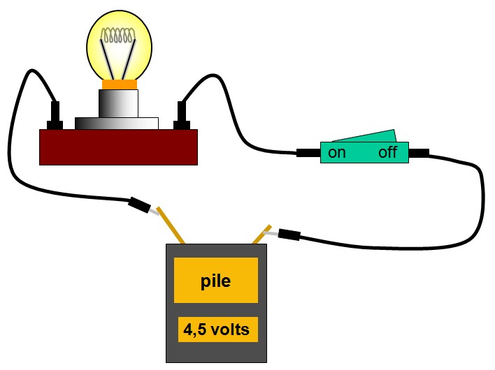
We have a power source, the battery. Then a switch, which we will abbreviate in C. And finally, a lamp, which we will abbreviate in L:
- if C is activated, the lamp L is on
- if C is deactivated, the lamp L is off
The state of L depends directly on the state of C. We can table this. We code the state inactive with the number 0 and the active state with the number 1:
| C | L |
|---|---|
| 0 | 0 |
| 1 | 1 |
Using 0 and 1 is a binary representation. Coding binary only knows two states: 0 or 1.
Coding of the content of a register on ARDUINO
A status register, PORTB for example, on an ARDUINO card, can be compared to a series of eight switches:
| b7 | b6 | b5 | b4 | b3 | b2 | b1 | b0 | LED 13 |
|---|---|---|---|---|---|---|---|---|
| 0 | x | x | x | x | x | x | x | 0 |
| 1 | x | x | x | x | x | x | x | 1 |
The letter x indicates a state that we do not manage. It can be 0 or 1.
We are only interested in the state of the switch b7 (for bit number 7).
This bit b7 manages the state of the LED which is on the ARDUINO card and directly connected to the physical connector 13, hence the name LED 13 in the table.
We have just reproduced, on the ARDUINO card, what is happening with the electrical circuit simple.
Combinatorial states
Combinatorial states designate the management of a device from several separate states. The best example, the circuit comes and goes for domestic lighting:
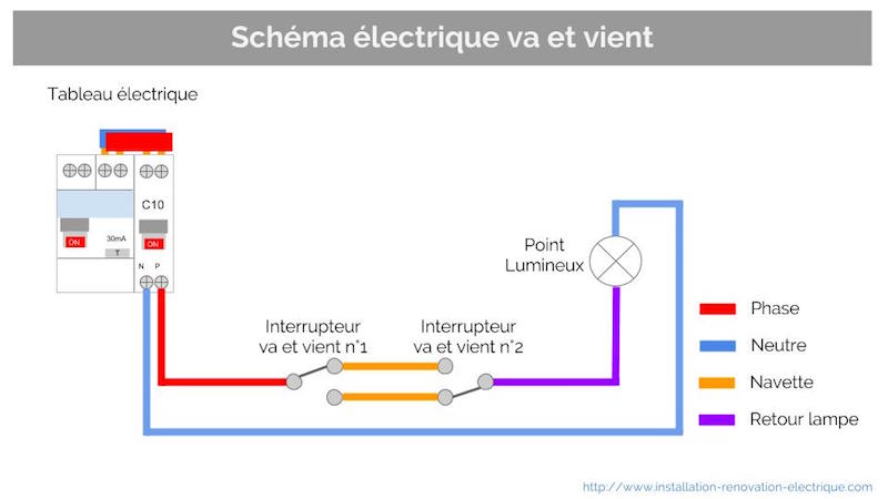
we will describe the state of the lamp L managed by these two switches:
| # state |
C1 | C2 | L |
|---|---|---|---|
| (0) | 0 | 0 | 1 |
| (1) | 0 | 1 | 0 |
| (2) | 1 | 0 | 0 |
| (3) | 1 | 1 | 1 |
We could number the states of c1 and c2 like this:
| # state |
C1 | C2 | L |
|---|---|---|---|
| (0) | 0 | 0 | 1 |
| (1) | 0 | 1 | 0 |
| (2) | 1 | 0 | 0 |
| (3) | 1 | 1 | 1 |
The first state has the number zero, the next the number 1 .. until the last state which has the number 3. For our two switches, there are only four possible states, therefore numbered from 0 to 3.
But why start numbering at zero and not at 1?
As Mr SPOCK would say in STAR TREK: "there is a logical reason..."
And let's explore this logic.
Binary decoding
Take state 3 of the circuit back and forth whose combination of states C1 and C2 is 11.
In decimal notation, we mention the order of the numbers in units, tens, hundreds, etc. Take a year: 2019. Mathematically, each digit of this number 2019 can be broken down like this. By convention, we note the power 'exp':
2019 = (9 * 10 exp 0) + (1 * 10 exp 1) + (0 * 10 exp 2) + (2 * 10 exp 3)
In mathematics:
- 10 power 0, which we noted
10 exp 0gives 1 - 10 power 1, which we noted
10 exp 1gives 10 - 10 power 2, which we noted
10 exp 2gives 100 - 10 power 3, which we noted
10 exp 3gives 1000
So we see that the exponent of 10 starts at 0 and goes up to 3. Again, we start from zero.
For binary coding, we will simply replace 10 by 2:
11 = (1 * 2 exp 0) + (1 * 2 exp 1)
- 2 power 0, noted
2 exp 0gives 1 - 2 power 1, noted
2 exp 1gives 2
The sum 1 + 2 gives in decimal 3, which corresponds to the decoding of the binary value 11.
First names randomly have a binary value 10010111 and let's see how to decode this in decimal.
We will start with the "units", that is to say the rightmost bit:
- 1 * 2 exp 0 = 1 * 1
- 1 * 2 exp 1 = 1 * 2
- 1 * 2 exp 2 = 1 * 4
- 0 * 2 exp 3 = 0 * 8
- 1 * 2 exp 4 = 1 * 16
- 0 * 2 exp 5 = 0 * 32
- 0 * 2 exp 6 = 0 * 64
- 1 * 2 exp 7 = 1 * 128
10010111 is recomposed into decimal: 1 + 2 + 4 + 16 + 128, which gives 151
in decimal.
Coding of the contents of the PORTB register on ARDUINO
We start from an ARDUINO card to which no circuit is connected. We put it under voltage and we just want to light the LED which is on the circuit in connection with terminal 13.
In this register PORTB, the bit which allows to activate or deactivate the lighting of this LED
is the last bit, the leftmost one. Here is the binary value to inject into the PORTB;
10000000 to turn on the LED, 00000000 to turn off the LED:
00000000corresponds to 0 in decimal coding10000000corresponds to 2 exp 7 (two power 7), or 128 in decimal coding.
$24 constant DDRB       \ Direction Data Register PORT B
$25 constant PORTB      \ data in PORT B
255 DDRB c!
128 PORTB c!            \ turn LED on
  0 PORTB c!            \ turn LED off
With FlashForth, you can enter a binary value if you precede it with the sign "%":
%10000000 PORTB c! \ turn LED on
The code sequences %10000000 PORTB c! and 128 PORTB c!
are equivalent and will have exactly the same effect.
Decimal to binary conversion and vice versa
The FORTH language knows how to manage numbers in almost any numerical base, from 2 to N, N can be any value. We can therefore use numbers in binary, in base 3, base 5, base 8, base 128, etc ...
A little exercise with gForth:
: numLoop ( ---)
    1000 0 do i . loop ;
128 base !
numLoop
Display:
numLoop 0 1 2 3 4 5 6 7 8 9 A B C D E F G H I J K L M N O P Q R S T U V W X Y Z
[ \ ] ^ _ ` a b c d e f g h i j k l m n o p q r s t u v w x y z { | } ~ ? ? '
ƒ " . ┼ ╬ ^ % S < O ? Z ? ? ' ' " " - - ~ T s > o ? z Y ¡ ¢ £ $ ¥ ¦ § ¨ © ª
« ¬ ® ¯ ° ± ² ³ ´ µ ¶ 10 11 12 13 14 15 16 17 18 19 1A 1B 1C 1D 1E 1F 1G 1H 1I
1J 1K 1L 1M 1N 1O 1P 1Q 1R 1S 1T 1U 1V 1W 1X 1Y 1Z 1[ 1\ 1] 1^ 1_ 1` 1a 1b 1c 1d
1e 1f 1g 1h 1i 1j 1k 1l 1m 1n 1o 1p 1q 1r 1s 1t 1u 1v 1w 1x 1y 1z 1{ 1| 1} 1~ 1
1? 1? 1' 1ƒ 1" 1. 1┼ 1╬ 1^ 1% 1S 1< 1O 1? 1Z 1? 1? 1' 1' 1" 1" 1 1- 1- 1~ 1T 1s
1> 1o 1? 1z 1Y 1 1¡ 1¢ 1£ 1$ 1¥ 1¦ 1§ 1¨ 1© 1ª 1« 1¬ 1 1® 1¯ 1° 1± 1² 1³ 1´ 1µ
1¶ 20 21 22 23 24 25 26 27 28 29 2A 2B 2C 2D 2E 2F 2G 2H 2I 2J 2K 2L 2M 2N 2O 2P
2Q 2R 2S 2T 2U 2V 2W 2X 2Y 2Z 2[ 2\ 2] 2^ 2_ 2` 2a 2b 2c 2d 2e 2f 2g 2h 2i 2j 2k
2l 2m 2n 2o 2p 2q 2r 2s 2t 2u 2v 2w 2x 2y 2z 2{ 2| 2} 2~ 2 2? 2? 2' 2ƒ 2" 2. 2┼
2╬ 2^ 2% 2S 2< 2O 2? 2Z 2? 2? 2' 2' 2" 2" 2 2- 2- 2~ 2T 2s 2> 2o 2? 2z 2Y 2 2¡
2¢ 2£ 2$ 2¥ 2¦ 2§ 2¨ 2© 2ª 2« 2¬ 2 2® 2¯ 2° 2± 2² 2³ 2´ 2µ 2¶ 30 31 32 33 34 35
36 37 38 39 3A 3B 3C 3D 3E 3F 3G 3H 3I 3J 3K 3L 3M 3N 3O 3P 3Q 3R 3S 3T 3U 3V 3W
3X 3Y 3Z 3[ 3\ 3] 3^ 3_ 3` 3a 3b 3c 3d .......
In FORTH, it is the BASE variable which thus determines in which base
Numeric are entered and processed numbers. The binary coding being in base 2,
to go to binary, you just have to put 2 in this BASE variable:
2 base !
And you're in binary! We can no longer enter other numbers than those made up of "0" and "1":
2 base !
101 110 + .   \ display 1011
To return to decimal, just type decimal:
2 base !
1011 decimal . \ display 1011
So, with the FORTH language, we have simple tools to display any value in decimal or binary. Let's create two words:
: bin. ( n ---)
    base @ >r
    2 base !
    0 <# # # # # # # # # #> type
    r> base ! ;
: dec. ( n ---)
    base @ >r
    decimal .
    r> base ! ;
For the word bin., we chose to display the binary value on 8 digits:
decimal
235 bin.   \ affiche 11101011
We are equipped to understand what happens when we carry out operations arithmetic or logic on binary values.
Logical operations in binary
In binary logic, there are only two logical operators: OR and AND. The operator OR is combined in two versions: OR which is inclusive, and XOR which is exclusive.
The negation of a logical value is carried out by NOT. Let's see in detail the states two-bit logic when we execute these different logical operators.
The AND operator
It performs a logical AND operation:
| C1 | C2 | AND |
|---|---|---|
| 0 | 0 | 0 |
| 0 | 1 | 0 |
| 1 | 0 | 0 |
| 1 | 1 | 1 |
Dans un circuit électrique, l'opérateur AND est semblable à deux interrupteurs en série:
In FORTH language, the word for performing a logical AND operation is and.
The OR operator
It performs a logical OR operation:
| C1 | C2 | OR |
|---|---|---|
| 0 | 0 | 0 |
| 0 | 1 | 1 |
| 1 | 0 | 1 |
| 1 | 1 | 1 |
In an electrical circuit, the operator OR is similar to two parallel switches:
In FORTH language, the word for performing a logical OR operation is or.
The NOT operator
The NOT operator reverses the logical state:
| C | NOT |
|---|---|
| 0 | 1 |
| 1 | 0 |
In FORTH language, the word used to perform a logical NOT operation is invert.
With the three binary operators AND, OR and NOT, we can process all combinations binaries. This is what we will see with some praptic examples.
Example of the NAND logic gate
The NAND logic function corresponds to the inverse of the AND operator:
| C1 | C2 | AND | NAND |
|---|---|---|---|
| 0 | 0 | 0 | 1 |
| 0 | 1 | 0 | 1 |
| 1 | 0 | 0 | 1 |
| 1 | 1 | 1 | 0 |
This NAND logic function does not exist in FORTH language. But as it was written earlier, with the logical operators AND, OR and NOT, we have the words to create this function:
: nand ( fl1 fl2 --- fl)
    and invert
  ;
Pfiouuu....! It's complicated huh?
Little exercise: managing three states
We are going to simulate a very special, totally imaginary circuit, which works like this:
- an output S which depends on three inputs A B C
- if no entry is active, S is inactive
- if only one entry A B or C is active, S is active
- if two entries among A B or C, S is active
- if the three entries A B and C are active, S is inactive
Here is Karnaugh's chart which describes the state of S:
| A B | |||||
|---|---|---|---|---|---|
| 00 | 01 | 11 | 10 | ||
| C | 0 | 0 | 1 | 1 | 1 |
| 1 | 1 | 1 | 0 | 1 | |
If we look at this table, we can make four groupings of states to 1.
First grouping
| A B | |||||
|---|---|---|---|---|---|
| 00 | 01 | 11 | 10 | ||
| C | 0 | 0 | 1 | 1 | 1 |
| 1 | 1 | 1 | 0 | 1 | |
In the rest of the article:
the logical operator OR will be noted +
the AND operator will be noted x
the NOT operator will be noted !
For this first grouping, the common states of A B C are formulated: !A x C
Second grouping
| A B | |||||
|---|---|---|---|---|---|
| 00 | 01 | 11 | 10 | ||
| C | 0 | 0 | 1 | 1 | 1 |
| 1 | 1 | 1 | 0 | 1 | |
For this second grouping, the common states of A B C are formulated: B x !C
Third grouping
| A B | |||||
|---|---|---|---|---|---|
| 00 | 01 | 11 | 10 | ||
| C | 0 | 0 | 1 | 1 | 1 |
| 1 | 1 | 1 | 0 | 1 | |
For this third grouping, the common states of A B C are formulated: A x !B
State formula of S
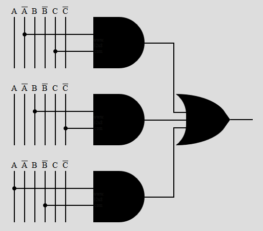
The logical equation for the state of output S will be:
( !A x C ) + ( B x !C ) + ( A x !B )
If we had to write a FORTH definition processing the output S, we could write:
variable A
variable B
variable C
: S-resolve ( --- fl)
  A @ invert   C @         and     \ ( !A x C )
  B @          C @ invert  and     \ ( B x !C )
  A @          B @ invert  and     \ ( A x B! )
  or or
  ;
Is there another way to set the state of the S output?
Yes. For that, let's go back to our first table. In this table we have only two O values to define the state of our S output:
| A B | |||||
|---|---|---|---|---|---|
| 00 | 01 | 11 | 10 | ||
| C | 0 | 0 | 1 | 1 | 1 |
| 1 | 1 | 1 | 0 | 1 | |
By taking exclusively into account these two state values 0 of the output S, the logical equation of the state of the output S could be rewritten in this form:
!( ( !A x !B x !C ) + ( A x B x C ) )
Which would give this definition in FORTH language:
variable A
variable B
variable C
: S-resolve ( --- fl)
  A @ invert  B @ invert  C @ invert  and and  \ ( !A x !B x !C )
  A @         B @         C @         and and  \ ( A x B C )
  or invert
  ;
The Karnaugh map (KM or K-map) is a method of simplifying Boolean algebra expressions. It uses Gray's code (also called reflected binary), which has the property main to vary only one bit between two successive words.