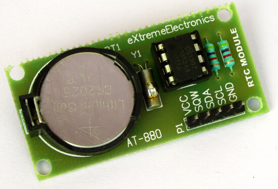
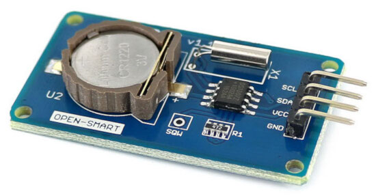
Module DS1307 RTC - real time clock
published: 9 November 2019 / updated 9 November 2019

Presentation
The DS1307 serial real-time clock (RTC) is a low-power, full binary-coded decimal (BCD) clock/calendar plus 56 bytes of NV SRAM. Address and data are transferred serially through an I2C, bidirectional bus. The clock/calendar provides seconds, minutes, hours, day, date, month, and year information. The end of the month date is automatically adjusted for months with fewer than 31 days, including corrections for leap year. The clock operates in either the 24-hour or 12-hour format with AM/PM indicator. The DS1307 has a built-in power-sense circuit that detects power failures and automatically switches to the backup supply. Timekeeping operation continues while the part operates from the backup supply.
Timekeeper Registers
The content of Timekeeper registers is in BCD (Binary Coded Decimal value) format.
There are total eight registers in timekeeper register for setting seconds, Minutes, Hours, Day, Date, Month, year and control.
Once we set the value of these registers, they will keep updating themselves, and we can read these registers to get updated values.
| ADDRESS | BIT 7 | BIT 6 | BIT 5 | BIT 4 | BIT 3 | BIT 2 | BIT 1 | BIT 0 | FUNCTION | RANGE |
|---|---|---|---|---|---|---|---|---|---|---|
| 00h | CH | 10 Seconds | Seconds | Seconds | 00–59 | |||||
| 01h | 0 | 10 Minutes | Minutes | Minutes | 00–59 | |||||
| 02h | 0 | 12 | 10 Hour |
10 Hour |
Hours | Hours | 1-12 +AM/PM 00-23 |
|||
| 24 | PM/ AM |
|||||||||
| 03h | 0 | 0 | 0 | 0 | 0 | DAY | Day | 01–07 | ||
| 04h | 0 | 0 | 10 Date | Date | Date | 01–31 | ||||
| 05h | 0 | 0 | 0 | 10 Month |
Month | Month | 01-12 | |||
| 06h | 10 Year | Year | Year | 00–99 | ||||||
| 07h | OUT | 0 | 0 | SQWE | 0 | 0 | RS1 | RS0 | Control | — |
| 08h–3Fh | RAM 56 x 8 | 00h–FFh | ||||||||
Control register
The DS1307 control register is used to control the operation of the SQW/OUT pin.
| BIT 7 | BIT 6 | BIT 5 | BIT 4 | BIT 3 | BIT 2 | BIT 1 | BIT 0 |
|---|---|---|---|---|---|---|---|
| OUT | 0 | 0 | SQWE | 0 | 0 | RS1 | RS0 |
Bit 7: Output Control (OUT). This bit controls the output level of the SQW/OUT pin when the square-wave output is disabled. If SQWE = 0, the logic level on the SQW/OUT pin is 1 if OUT = 1 and is 0 if OUT = 0. On initial application of power to the device, this bit is typically set to a 0.
Bit 4: Square-Wave Enable (SQWE). This bit, when set to logic 1, enables the oscillator output. The frequency of the square-wave output depends upon the value of the RS0 and RS1 bits. With the square-wave output set to 1Hz, the clock registers update on the falling edge of the square wave. On initial application of power to the device, this bit is typically set to a 0.
Bits 1 and 0: Rate Select (RS[1:0]). These bits control the frequency of the square-wave output when the square-wave output has been enabled. The following table lists the square-wave frequencies that can be selected with the RS bits. On initial application of power to the device, these bits are typically set to a 1.
| RS1 | RS0 | SQW/OUT OUTPUT | SQWE | OUT |
|---|---|---|---|---|
| 0 | 0 | 1Hz | 1 | X |
| 0 | 1 | 4.096kHz | 1 | X |
| 1 | 0 | 8.192kHz | 1 | X |
| 1 | 1 | 32.768kHz | 1 | X |
| X | X | 0 | 0 | 0 |
| X | X | 1 | 0 | 1 |
DS1307 Specifications
- I2C Interface RTC IC
- Operating Voltage: 5V
- Less than 500nA current when operating with battery
- 56 bytes SVRAM
- Operates in power or battery mode
- Programmable square wave output pin
- Available in PDIP and SO package