The LORA REYAX RYLR896 transmitter
published: 26 September 2020 / updated 10 October 2020

Articles using LoRa:
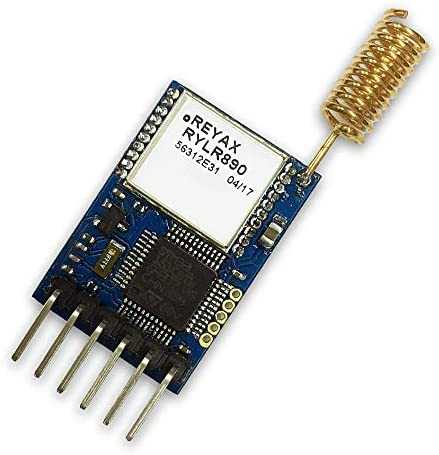
Product description
The RYLR896 transceiver module feature the Lora long range modem that provides ultra-long range spread spectrum communication and high interference immunity whilst minimising current consumption. The RYLR896 is certified by NCC and FCC.
Features
- Semtech SX1276 Engine
- Excellent blocking immunity
- Low receive current
- High sensitivity
- Control easily by AT commands
- 127 dB Dynamic Range RSSI
- Designed with PCB integrated antenna
- AES128 Data encryption
Applications
- IoT Applications
- Mobile Equipment
- Home Security
- Industrial Monitoring and Control Equipment
- Car Alarm
Pin description
| Pin | Name | I/O | Condition | |
|---|---|---|---|---|
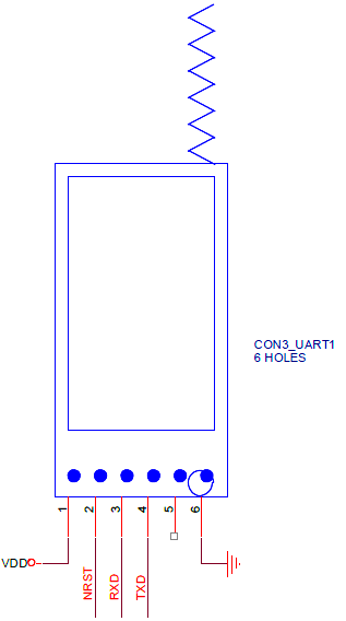 |
1 | VDD | I | Power Supply |
| 2 | NRST | I | RESET(Active Low)100KΩ Internal pull up, Pull down at least 100ms |
|
| 3 | RXD | I | UART Data Input | |
| 4 | TXD | O | UART Data Output | |
| 5 | NC | |||
| 6 | GND | Ground |
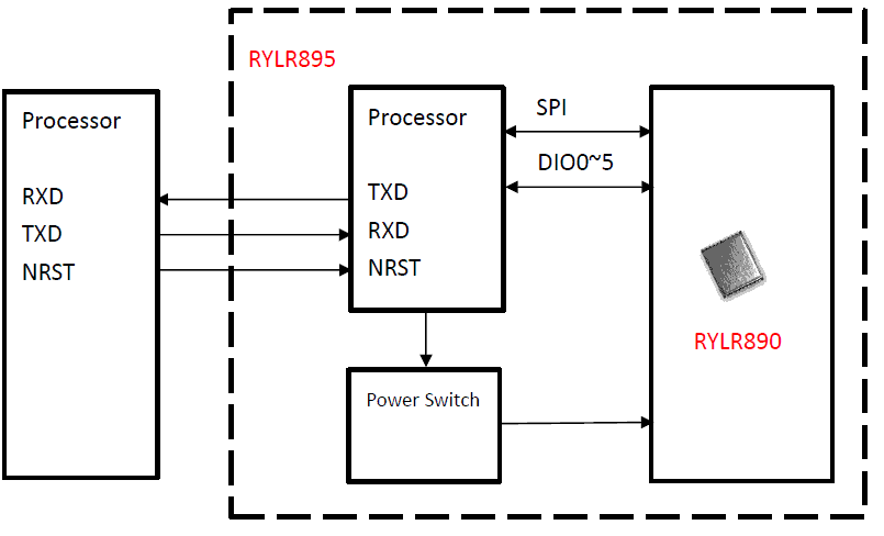
Block diagram
Specification
| Item | Min. | Typical | Max. | Unit | Condition |
|---|---|---|---|---|---|
| VDD Power Supply | 2 | 3.3 | 3.6 | V | VDD |
| RF Output Power Range | -4 | 15 | dBm | ||
| Filter insertion loss | 1 | 2 | 3 | dB | |
| RF Sensitivity | -148 | dBm | |||
| RF Input Level | 10 | dBm | |||
| Frequency Range | 862 | 868/915 | 1020 | MHz | |
| Frequency Accuracy | ±2 | ppm | |||
| Communication Range * | 4.5 | 15 | KM | Depend on RF parameter | |
| Transmit Current | 43 | mA | RFOP = +15 dBm | ||
| Receive Current | 16.5 | mA | AT+MODE=0 | ||
| Sleep Current | 0.5 | uA | AT+MODE=1 | ||
| Baud rate | 300 | 115200 | 115200 | bps | 8, N, 1 |
| Digital Input Level High | 0.7*VDD | VDD | V | VIH | |
| Digital Input Level Low | 0 | 0.3*VDD | V | VIL | |
| Digital Output Level High | 0.9 | VDD | V | VOH | |
| Digital Output Level Low | 0.1 | V | VOL | ||
| Cycling (erase / write) EEPROM data memory | 300 | K | Cycles | ||
| Weight | 7 | g | |||
| Operating Temperature | -40 | 25 | +85 | ˚C |
The LoRa Alliance has defined two frequency bands for the usage of LoRa technology in Europe. These bands are EU433 from 433.05 to 434.79 MHz and EU863 from 863 to 870 MHz.
The EU863-870 band can be used in any region where the ISM radio spectrum is defined by the ETSI 307 standard. The end devices in this band will operate from 863 to 870 MHz and use a channel data structure to store the information of at least 16 channels. The channels in this band can be attributed freely by the operator; however the three default channels; 868.10, 868.30, 868.50 are mandatory to be implemented in every EU863 end-device. Other channels can be freely distributed across the allowed frequency range on a network per network basis.
Lora AT command guide
Apply for:
- RYLR405
- RYLR406
- RYLR895
- RYLR896
The sequence of using AT command
- Use “AT+ADDRESS” to set ADDRESS. The ADDRESS is regard as the identification of transmitter or specified receiver.
- Use “AT+NETWORKID” to set the ID of Lora network. This is a Group function. Only by setting the same NETWORKID can the modules communicate with each other. If the ADDRESS of specified receiver is belong to different group, it is not able to communicate with each other. The recommend value: 1~15
- Use” AT+BAND” to set the center frequency of wireless band. The transmitter and the receiver are required to use the same frequency to communicate with each other.
- Use” AT+PARAMETER” to set the RF wireless parameters. The transmitter and
the receiver are required to set the same parameters to communicate with each other.
The parameters of which as follows:
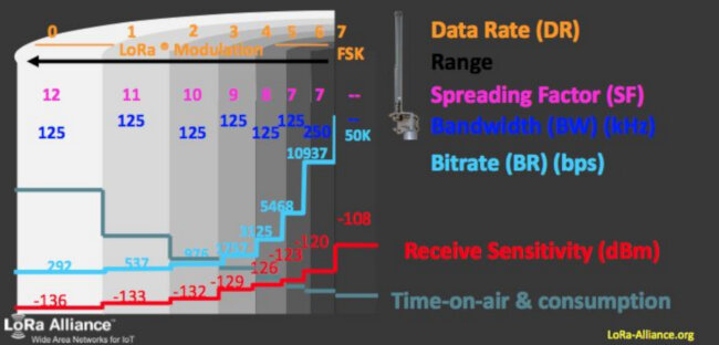
- <Spreading Factor>: The larger the SF is, the better the sensitivity is. But the transmission time will take longer.
- <Bandwidth>: The smaller the bandwidth is, the better the sensitivity is. But the transmission time will take longer.
- <Coding Rate>: The coding rate will be the fastest if setting it as 1.
- <Programmed Preamble>: Preamble code. If the preamble code is bigger, it will result in the less opportunity of losing data. Generally preamble code can be set above 10 if under the permission of the transmission time. Communication within 3 km: Recommend to set “AT + PARAMETER = 10,7,1,7” More than 3 km: Recommend to set “ AT + PARAMETER = 12,4,1,7”
- Use “AT+SEND” to send data to the specified ADDRESS. Please use “Lora Modem Calculator Tool” to calculate the transmission time. Due to the program used by the module, the payload part will increase more 8 bytes than the actual data length.
It is required to key in “enter” or “\r\n” in the end of all AT Commands.
Add“ ? ”in the end of the commands to ask the current setting value.
It is required to wait until the module replies +OK so that you can execute the next AT command.
ADDRESS
Set the ADDRESS of module.
Each LoRa transmission module must have a personal address.
| syntax | response |
|---|---|
| AT+ADDRESS=<address> | +OK |
| AT+ADDRESS=? | +ADDRESS=22 |
<Address>=0~65535(default 0)
Example: Set the address of module as 22:
AT+ADDRESS=22
The settings will be memorized in EEPROM.
AT
| syntax | response |
|---|---|
| AT | +OK |
BAND
Set RF Frequency.
| syntax | response |
|---|---|
| AT+BAND=<parameter> | +OK |
| AT+BAND=? | +BAND=868500000 |
<parameter>is the RF Frequency, Unit is Hz: 915000000Hz(default: RYLY89x)
Example : Set the frequency as 868500000Hz:
AT+BAND=868500000
CPIN
Set the AES128 password of the network.
| syntax | response |
|---|---|
| AT+CPIN=<password> | +OK |
| AT+CPIN=? | +CPIN=FABC0002EEDCAA90FABC0002EEDCAA90 |
Password:
An 32 character long AES password From 00000000000000000000000000000001 to FFFFFFFFFFFFFFFFFFFFFFFFFFFFFFFF.
Only by same password can the data be recognized. After resetting, the previously password will disappear.
Example: Set the password as below: FABC0002EEDCAA90FABC0002EEDCAA90
AT+CPIN=FABC0002EEDCAA90FABC0002EEDCAA90
CRFOP
Set the RF output power.
| syntax | response |
|---|---|
| AT+CRFOP=<power> | +OK |
| AT+CRFOP=? | +CRFOP=10 |
Power:
Between 0..15, 15dBm(default)
Example: Set the output power as 10dBm
AT+CRFOP=10
FACTORY
Set all current parameters to manufacturer defaults.
| syntax | response |
|---|---|
| AT+FACTORY | +FACTORY |
IPR
Set the UART baud rate.
| syntax | response |
|---|---|
| AT+IPR=<parameter> | +OK |
| AT+IPR=? | +IPR=38400 |
UART baud parameter:
- 300
- 1200
- 4800
- 9600
- 19200
- 28800
- 38400
- 57600
- 115200 (default)
The settings will be memorized in EEPROM.
MODE
Set the work mode.
| syntax | response |
|---|---|
| AT+MODE=<parameter> | +OK |
| AT+MODE=? | +MODE=1 |
Parameter:
- 0:Transmit and Receive mode (default).
- 1:Sleep mode.
Forth code for FlashForth:
\ Set the work mode, must be one of
\ 0 (defalt) Transmit and Receive mode
\ 1 Sleep mode
: (ATmode)  ( str ---)
    ." AT+MODE=" type ;
: .ATmode" ( --- <string>)
    postpone s"
    postpone (ATmode)
  ; immediate
\ example:
\ .ATmode" 0"
NETWORKID
Set the network ID.
| syntax | response |
|---|---|
| AT+NETWORKID=<Network ID> | +OK |
| AT+NETWORKID=? | +NETWORKID=6 |
Network ID: 0~16(default 0)
Example: Set the network ID as 6
AT+NETWORKID=6
The settings will be memorized in EEPROM.
The”0”is the public ID of Lora. It is not recommend to set 0 to make the distinction of NETWORK.
Forth code for FlahsForth:
\ Set the network ID
\ must be 0..16
\ 0 is the public ID of Lora
: (ATnetworkid) ( str ---)
    ." AT+NETWORKID=" type ;
: .ATnetworkid" ( ---)
    postpone s"
    postpone (ATnetworkid)
  ; immediate
\ example:
\ .ATnetworkid" 6"
PARAMETER
Set the RF parameters.
| syntax | response |
|---|---|
| AT+PARAMETER=<Spreading Factor>, <Bandwidth>,<Coding Rate>, <Programmed Preamble> | +OK |
| AT+PARAMETER=? | +PARAMETER=7,3,4,5 |
Parameters:
- Spreading Factor / facteur d'étalement
- 7~12, (default 12)
- Bandwidth / largeur de bande (0~9):
- 0 : 7.8KHz (not recommended, over spec.)
- 1 : 10.4KHz (not recommended, over spec.)
- 2 : 15.6KHz
- 3 : 20.8 KHz
- 4 : 31.25 KHz
- 5 : 41.7 KHz
- 6 : 62.5 KHz
- 7 : 125 KHz (default).
- 8 : 250 KHz
- 9 : 500 KHz
- Coding rate
- 1~4, (default 1)
- Programmed Preamble
- 4~7 (default 4)
Spreading Factor / facteur d'étalement
| Spreading factor facteur d'étalement |
Bitrate / débit |
|---|---|
| 7 | 5469 bps |
| 8 | 3125 bps |
| 9 | 1758 bps |
| 10 | 977 bps |
| 11 | 537 bps |
| 12 | 293 bps |
Coding rate
LoRa modulation also adds a forward error correction (FEC) in every data transmission. This implementation is done by encoding 4-bit data with redundancies into 5-bit, 6-bit, 7-bit, or even 8-bit. Using this redundancy will allow the LoRa signal to endure short interferences. The Coding Rate value need to be adjusted according to conditions of the channel used for data transmission. If there are too many interference in the channel, then it’s recommended to increase the value of Coding Rate.
However, the rise in CR value will also increase the duration for the transmission.
Example: Set the parameters as below:
<Spreading Factor> 7,<Bandwidth> 20.8KHz,
<Coding Rate> 4,<Programmed Preamble>5,
AT+PARAMETER=7,3,4,5
RCV
Show the received data.
| syntax | response |
|---|---|
| AT+RCV=<Address>,<Length>,<Data>,<RSSI>,<SNR> |
This command is not to be used directly. It results from a transmission successful.
<Address>: Transmitter Address ID.
<Length>Data Length.
<Data>Data.
<RSSI> Received Signal Strength Indicator.
<SNR> Signal-to-noise ratio.
Example: Module received the ID Address 50 send 5 bytes data, Content is HELLO
string ,RSSI is -99dBm, SNR is 40, It will show as below:
+RCV=50,5,HELLO,-99,40
RSSI
The Received Signal Strength Indication (RSSI) is the received signal power in milliwatts and is measured in dBm.
This value can be used as a measurement of how well a receiver can “hear” a signal from a sender.
The RSSI is measured in dBm and is a negative value.
The closer to 0 the better the signal is.
Typical LoRa RSSI values are:
- RSSI minimum = -120 dBm.
- if RSSI=-30dBm: signal is strong.
- if RSSI=-120dBm: signal is weak.
SNR
Signal-to-Noise Ratio (SNR) is the ratio between the received power signal and the noise floor power level.
The noise floor is an area of all unwanted interfering signal sources which can corrupt the transmitted signal and therefore re-transmissions will occur.
- if SNR is greater than 0, the received signal operates above the noise floor.
- if SNR is smaller than 0, the received signal operates below the noise floor.
Normally the noise floor is the physical limit of sensitivity, however LoRa works below the noise level.
Typical LoRa SNR values are between: -20dB and +10dB
A value closer to +10dB means the received signal is less corrupted.
LoRa can demodulate signals which are -7.5 dB to -20 dB below the noise floor.
RESET
Software RESET.
| syntax | response |
|---|---|
| AT+RESET | +OK |
SEND
Send data to the appointment Address.
| syntax | response |
|---|---|
| AT+SEND=<Address>,<Payload Length>,<Data> | +OK |
| AT+SEND=? | +SEND=50,5,HELLO |
<Address>0~65535, When the
<Address> is 0, it will send data to all address (From 0 to 65535.)
<Payload Length>Maximum 240bytes
<Data>ASCII Format
Example: Send HELLO string to the Address 50:
AT+SEND=50,5,HELLO
Forth code for FlashForth:
\ convert a number to a Forth code for FlahsForth:decimal string
: .#s ( n ---)
    base @ >r
    0 <# #s #> type
    r> base !
  ;
\ Send data to the appointment Address n
\ ex: AT+SEND=50,5,HELLO
: (ATsend) ( LORAaddress str ---)
    ." AT+SEND="
    rot .#s    \ convert LORAaddress to string and type
    [char] , emit
    dup .#s    \ convert str len to string and emit
    [char] , emit
    type ;
: .ATsend" ( LORAaddress ---)
    postpone s"
    postpone (ATsend)
  ; immediate
\ exemple (COMPILE ONLY)
\ : lights.on ( ---)
\    120 .ATsend" LIGHTS ON" ;
VER
To inquire the firmware version
Error result codes
- +ERR=1 there is not “enter” or $0D $0A in the end of the AT Command
- +ERR=2 the head of AT command is not “AT” string
- +ERR=3 there is not “=”symbol in the AT command
- +ERR=4 unknow command
- +ERR=10 TX is over times
- +ERR=11 RX is over times
- +ERR=12 CRC error
- +ERR=13 TX data more than 240bytes
- +ERR=15 Unknow error