The MAX7219 module - LED matrix 8x8
published: 28 April 2024 / updated 28 April 2024

article: 05 nov. 2019 / mis à jour 24 nov. 2019
Dependancys
To use the MAX7219 module via the SPI interface, you must download and compile the code:
Words to drive the SPI module on the ATmega2560
The 8x8 LED matrix
Here is our 8x8 LED matrix:
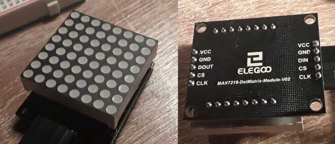
The display consists of 8 rows of 8 LEDs, for a total of 64 LEDs.
On the back of the display, 5 connectors on the right and 5 connectors on the left. All connectors have the same indications, except the 3rd connector which is marked DIN on the right, DOUT on the left.
Meaning of the connectors:
- VCC 5 Volts input (+)
- GND 0 Volts input (-) (GND = Ground)
- DIN / DOUT DIN for data entry, DOUT for data output
- CS connector for selection (CS = Chip Select)
- CLK connector for synchronization signal (CLK = CLocK)
With the only DIN, CS and CLK connectors we have to manage the 64 LEDs of this display ...
Features of the 8x8 display
If you only use one 8x8 LEDs display on your ARDUINO board, the power supply USB may be sufficient. But it is strongly recommended to feed the display via a separate 5 Volt power supply.
The GND connector of the 8x8 LEDs display must be connected to a GND terminal of the ARDUINO card.
The display is controlled by a circuit referenced MAX7219. This component has of 2x eight parallel outputs managing the matrix of LEDs. It also has an interface of Serial Peripheral Interface SPI serial communication interface will see the features further.
Organization of the matrix 8x8 LEDs:
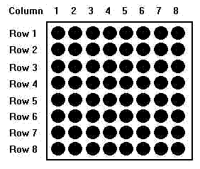
No indication on the display can determine in which direction to orient this display.
Some articles on the Internet show that it is possible to serialize several 8x8 LEDs displays:
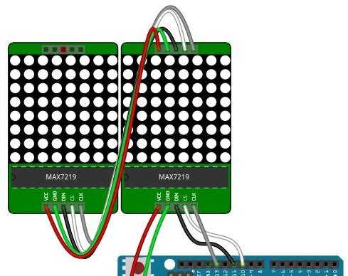
Having only one 8x8 LED display, we can not test the connection of several 8x8 LED arrays in series.
We will consider that the bottom of the display corresponds to the input connectors, placed at the bottom. The five output connectors are placed at the top.
Connection to the ARDUINO board
| 8x8 LED matrix |
ARDUINO |
|---|---|
| VCC | +5V |
| GND | GND |
| DIN | MOSI |
| CS | SS |
| CLK | SCK |
| DOUT* | MISO |
* optional - DOUT output is connected:
- for a single MAX7219 module: at the MISO terminal of the ARDUINO board
- for several MAX7219 modules; to the DIN terminal of the following MAX7219 module. Terminal DOUT of the last MAX7219 module is connected to the MISO board of the ARDUINO board.
The MAX7219 chip
It's a chip built into our 8x8 LED display.
The MAX7219 chip divides a set of 64 LEDs into eight columns (“digits”) of eight LEDs each. The columns are numbered 1 through 8, and each LED within a column is represented by a single bit in that column’s register.
Specification of LED Matrix
Operating Voltage: DC 4.7V – 5.3V
Typical Voltage: 5V
Operating Current: 320mA
Max Operating Current: 2A
Operating Temperature: 0 ℃ – 50 ℃
Typical Temperature: 25 ℃
Hardware Installation
Example of connecting the MAX7219 module to an ARDUINO MEGA board:
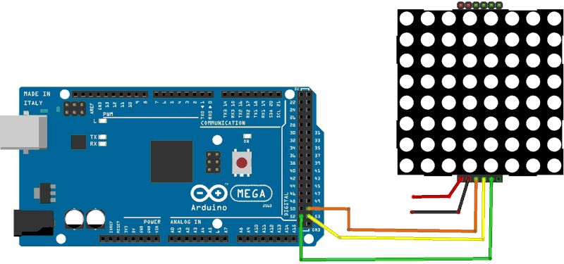
The power supply of the MAX7219 module must be carried out in preference to a 5-volt power supply separated from that of the ARDUINO card.
Organization of the matrix
Each row corresponds to an address. Each address can receive a byte in the hexadecimal interval [00..ff].
Each column corresponds to a bit in the byte transmitted as data.
So, the lighting of a row will be done by transmitting two bytes:
- addr: Address of the row to be managed, in the hexadecimal range [01..08]. The value $ 01 is the one marked row1< b> above.
- data: data to put in the row, in the hexadecimal range [00..ff]. The $00 value turns off all the LEDs, the $ff value turns on all the LEDs.
Serial-Data Format (16 Bits)
Here's how addr data is organized:
| D15 | D14 | D13 | D12 | D11 | D10 | D9 | D8 | D7 | D6 | D5 | D4 | D3 | D2 | D1 | D0 |
|---|---|---|---|---|---|---|---|---|---|---|---|---|---|---|---|
| X | X | X | X | ADDRESS | MSB --- DATA --- LSB | ||||||||||
- addr can only take hexadecimal values [00..0f]. These are the bits D8 to D11 marked ADDRESS in the box above.
- data follows addr
Les adresses $0d et $0e ne sont pas exploitées.
Here are the actions performed by the addresses addr:
| REGISTER | ADDRESS | HEX CODE |
||||
|---|---|---|---|---|---|---|
| D15 D12 | D11 | D10 | D9 | D8 | ||
| No-Op | X | 0 | 0 | 0 | 0 | $00 |
| Digit 0 | X | 0 | 0 | 0 | 1 | $01 |
| Digit 1 | X | 0 | 0 | 1 | 0 | $02 |
| Digit 2 | X | 0 | 0 | 1 | 1 | $03 |
| Digit 3 | X | 0 | 1 | 0 | 0 | $04 |
| Digit 4 | X | 0 | 1 | 0 | 1 | $05 |
| Digit 5 | X | 0 | 1 | 1 | 0 | $06 |
| Digit 6 | X | 0 | 1 | 1 | 1 | $07 |
| Digit 7 | X | 1 | 0 | 0 | 0 | $08 |
| Decode Mode | X | 1 | 0 | 0 | 1 | $09 |
| Intensity | X | 1 | 0 | 1 | 0 | $0a |
| Scan Limit | X | 1 | 0 | 1 | 1 | $0b |
| Shutdown | X | 1 | 1 | 0 | 0 | $0c |
| Display Test | X | 1 | 1 | 1 | 1 | $0f |
- addr $00 without action
- addr $01..$08 row of LEDs to light, data $ 00 .. $ ff
- addr $09 decoding mode: $ 00 = no decoding; $ 01 = BCD decoding (do not use for 8x8 LED array
- addr $0a display intensity setting: $ 00 .. $ 0f, $ 00 being the minimum intensity, $ 0f being the maximum intensity;
- addr $0b limit range of rows to display: $ 00 .. $ 07; put $ 07 to handle all the LED array
- addr $0c disables the display: $ 00 .. $ 01; put $ 01 to make the LEDs visible.
- addr $0f tests the display. Allows you to check the status of all the LEDs. Values: $00 normal operations; $ 01 LED test mode.
Here are the words to manage the 8x8 LED matrix via the MAX7219 module.
The word max7219.send passes two bytes to the MAX7219 module:
: max7219.send ( c1 c2 -- )
    mSS1 slave.select
    swap spi.csend spi.csend
    mSS1 slave.deselect
  ;
The words disp.normal and disp.shutdown respectively allow
to use the normal or disabled display mode:
: disp.normal   ( -- )
    $0c $01 max7219.send ;
: disp.shutdown ( -- )
    $0c $00 max7219.send ;
The words disp.test.on and disp.test.off allow you to activate or
disable the test mode of the LEDs:
: disp.test.on  ( -- )
    $0f $01 max7219.send ;
: disp.test.off ( -- )
    $0f $00 max7219.send ;
| MODE | ADDRESS CODE |
REGISTER DATA | |||||||
|---|---|---|---|---|---|---|---|---|---|
| D7 | D6 | D5 | D4 | D3 | D2 | D1 | D0 | ||
| Shutdown Mode | X | X | X | X | X | X | X | X | 0 |
| Normal Operation | X | X | X | X | X | X | X | X | 1 |
The word disp.no.op has no action. It is used in the case of linked MAX7219 modules.
: disp.no.op      ( -- )
    $00 $00  max7219.send ;
The word disp.intensity is used to set the intensity of the LEDs in
normal display. This setting affects all the LEDs of the 8x8 matrix.
: disp.intensity  ( c -- )
    $0a swap max7219.send ;
The word disp.decode is used to select the decoding mode of the MAX7219 module.
: disp.decode     ( c -- )
    $09 swap max7219.send ;
The word disp.scan.limit limits the action to only certain rows of LEDs.
: disp.scan.limit ( c -- )
    $0b swap max7219.send ;
| SCAN LIMIT | REGISTER DATA | HEX CODE |
|||||||
|---|---|---|---|---|---|---|---|---|---|
| D7 | D6 | D5 | D4 | D3 | D2 | D1 | D0 | ||
| Display digit 0 only | X | X | X | X | X | 0 | 0 | 0 | $00 |
| Display digits 0 & 1 | X | X | X | X | X | 0 | 0 | 1 | $01 |
| Display digits 0 1 2 | X | X | X | X | X | 0 | 1 | 0 | $01 |
| Display digits 0 1 2 3 | X | X | X | X | X | 0 | 1 | 1 | $03 |
| Display digits 0 1 2 3 4 | X | X | X | X | X | 1 | 0 | 0 | $04 |
| Display digits 0 1 2 3 4 5 | X | X | X | X | X | 1 | 0 | 1 | $05 |
| Display digits 0 1 2 3 4 5 6 | X | X | X | X | X | 1 | 1 | 0 | $06 |
| Display digits 0 1 2 3 4 5 6 7 | X | X | X | X | X | 1 | 1 | 1 | $07 |
And finally, the word disp.set.digit
: disp.set.digit  ( cbits cdigit -- )
    swap max7219.send ;
This word is used in the display test examples below.
Some display tests
The word disp-test-1 is used to test the display of the LEds of the matrix
8x8:
: disp-test-1 ( -- ) \ all LEDs on full, 232mA needed
    spi.init
    disp.test.on
    begin key? until
    disp.test.off
    spi.close
  ;
Here is what gives the execution of the word disp-test-1:
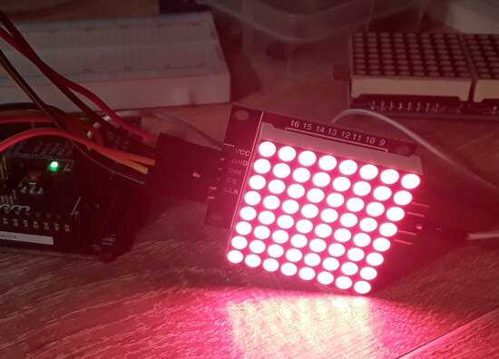
Execution is interrupted by pressing a key on the keyboard.
The word disp-test-2 turns on the 4 left LEDs of the first row:
: disp-test-2 ( -- ) \ left 4 LEDs on first row, 42mA needed
    spi.init
    disp.normal
    $03 disp.intensity
    $00 disp.scan.limit
    $f0 $01 disp.set.digit
    begin key? until
    disp.shutdown
    spi.close
  ;
Here is what gives the execution of the word disp-test-2:
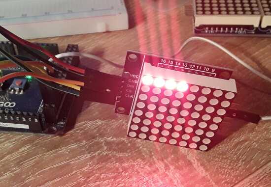
Execution is interrupted by pressing a key on the keyboard.
The word disp-test-3 displays a smiley character:
: disp-test-3 ( -- ) \ draw face, 18mA needed
    spi.init
    disp.normal
    $01 disp.intensity
    $07 disp.scan.limit
    $00 disp.decode
    %00000000 $01 disp.set.digit
    %01100110 $02 disp.set.digit
    %00000000 $03 disp.set.digit
    %00011000 $04 disp.set.digit
    %00011000 $05 disp.set.digit
    %10000001 $06 disp.set.digit
    %01000010 $07 disp.set.digit
    %00111100 $08 disp.set.digit
    begin key? until
    disp.shutdown
    spi.close
  ;
Here is what gives the execution of the word disp-test-3:
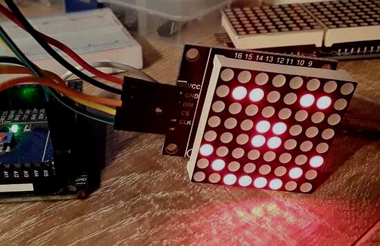
Execution is interrupted by pressing a key on the keyboard.