Module 4 relays
published: 12 November 2019 / updated 14 November 2019

Presentation
The relay module is an electrically operated switch that allows you to turn on or off a circuit using voltage and/or current much higher than a microcontroller could handle. There is no connection between the low voltage circuit operated by the microcontroller and the high power circuit. The relay protects each circuit from each other.
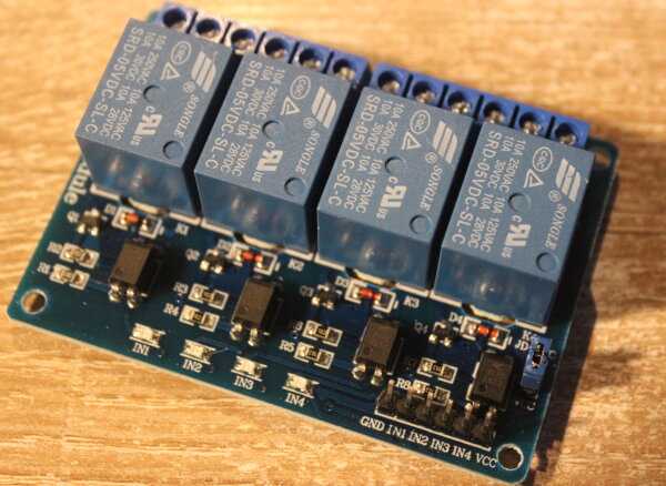
This relay module is 5V active low. Relay output maximum contact is AC250V 10A and DC30V 10A.
Standard interface can be directly connected with microcontrollers.
Working status indicator lights are conducive to the safe use.
4-channel relay interface board, which can be controlled directly by a wide range of microcontrollers such as Arduino, AVR, PIC, ARM, PLC, etc. It is also able to control various appliances and other equipments with large current.
Widely used for all MCU control, industrial sector, PLC control, smart home control.
4 relay module connection
The location of this connector may vary depending on the module brands available. The general order of the connectors is as follows:
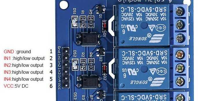
- GND corresponds to the ground and must be connected to a GND terminal on the ARDUINO board;
- VCC 5V DC corresponds to the 5V power supply and must be connected to a 5V terminal on the ARDUINO board;
- IN1 IN2 IN3 IN4 correspond to relay activation from the ARDUINO board. These entries must be connected to the terminals of an output PORT on an ARDUINO board.
In order for a relay to be at rest, a signal must be sent high on the terminal corresponding to this relay. Example, for a 4 relay board connected to bits b0 to b3 out of PORTB:
\ PORTB 37 constant PORTB \ Port B Data Register 36 constant DDRB \ Port B Data Direction Register : defPin: ( PORTx mask ---| create c, c, \ compile PORT and min mask does> dup c@ \ push pin mask swap 1+ c@ \ push PORT ; \ definition RELAYx eeprom PORTB %00000001 defPin: RELAY1 PORTB %00000010 defPin: RELAY2 PORTB %00000100 defPin: RELAY3 PORTB %00001000 defPin: RELAY4 : init.RELAYS ( ---) RELAY1 drop RELAY2 drop + RELAY3 drop + RELAY4 drop + dup DDRB mset PORTB mset ;--- mask port)
The word init.RELAYS initializes the four least significant bits on
the PORTB by putting all the relays at rest.
If we tested these outputs of the PORTB, we would see that they are in the state 5V, ie to the high state. Truth table of a relay activation output:
| pin | RELAY |
|---|---|
| 0 | ON |
| 1 | OFF |
For this reason, the relay activation and deactivation words are defined as follows:
: relay.ON (---) mclr ; \ turn relay ON : relay.OFF (---) mset ; \ turn relay OFF
In fact, we do exactly the opposite of what is done to turn on and off LEDs connected to these same outputs b0 to b3 of PORTB on the ARDUINO board.
Relay outputs
Table of truth of the outputs of a relay:
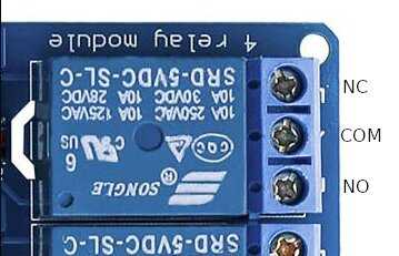
| input | NC | NO |
|---|---|---|
| 0 | ON | OFF |
| 1 | OFF | ON |
The COM terminal will correspond to one input, the other NC terminals and NO corresponding to outputs.